MendelMax3 - Lower LED Mount
My new MendelMax3 came with nice LEDs which indicate heating progress (they may indicate other things - I haven’t found out yet).
However, there doesn’t seem to be any clear or obvious way to mount the included LED strips. So I decided to make an LED mount.
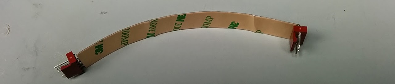
I like to use connectors (rather than soldered wires), so I decided to use some Molex KK style connectors. A 5 pin connector with one of the pins pulled lines up nicely with the solder pads on the LED strip. Due to space constraints, I had to bend the pins on one, like so:


I just realized that my LED strips came unsoldered. If you have the soldered versions and would like some changes made, please let me know. I modified the frame mount so that you can insert the wires if they’re already soldered onto the LED strip.
Here’s the LED strip with the input on the right and output on the left:
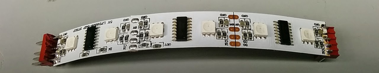
Another view from behind (I obviously need to improve my lighting - sorry about that):
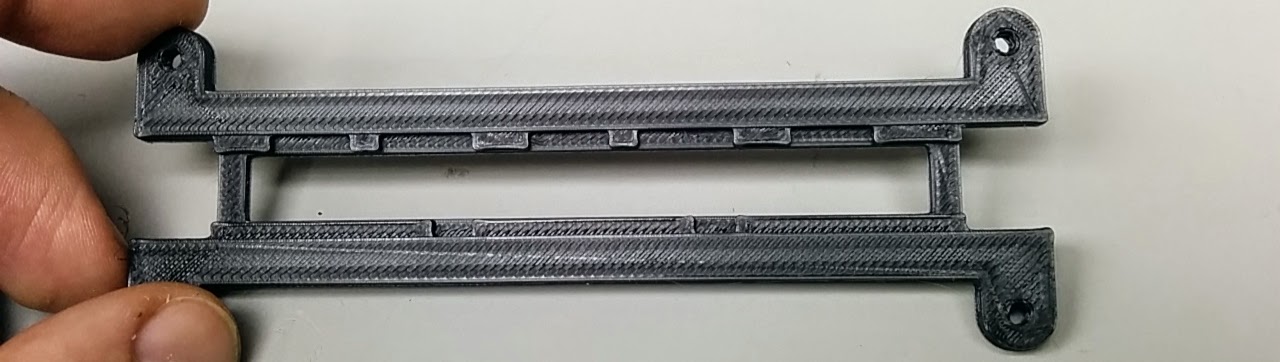
Here’s a photo of the spacer. My little LED strip seemed to be near the end of 2 strips soldered together and had a few extra resistors. So I placed some notches in the spacer to accomodate this. The notches are designed to go against the top of the LED strip (when you read the writing on the strip the right way around). In my case, the writing points down, so the notches would go along the bottom. If you got an LED strip without any extra resistors, then it doesn’t matter which way the spacer is mounted.
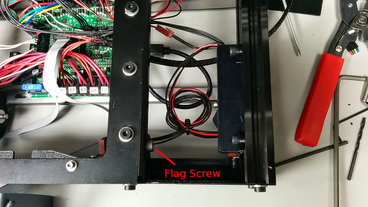
Here it is all put together. The piece that looks like a flag in the middle mounts on rightmost Y-rail extrusion. It was designed to clear the wheels on the Y-axis, so when you screw in the bolt, push down on the top to ensure its as low as possible. The tab on the right hand sound mounts on the bottom right 2020 extrusion.
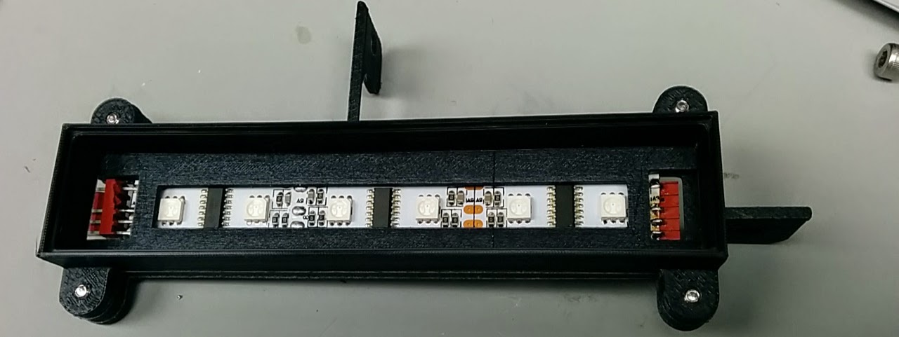
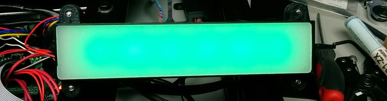
The white plastic piece (included with the MM3 should fit right onto the end. I used a couple of pieces of electrical tape to secure it in place. Hot glue or silicon caulk could also be used. Here’s the LED unit lit up.
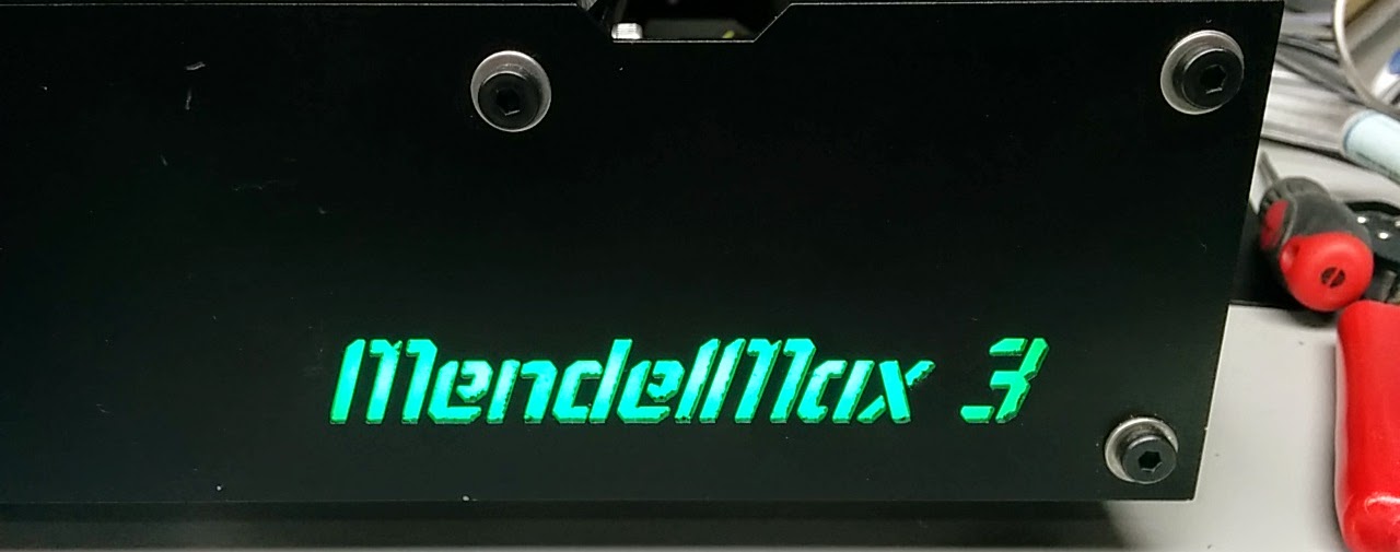
And here it is installed:
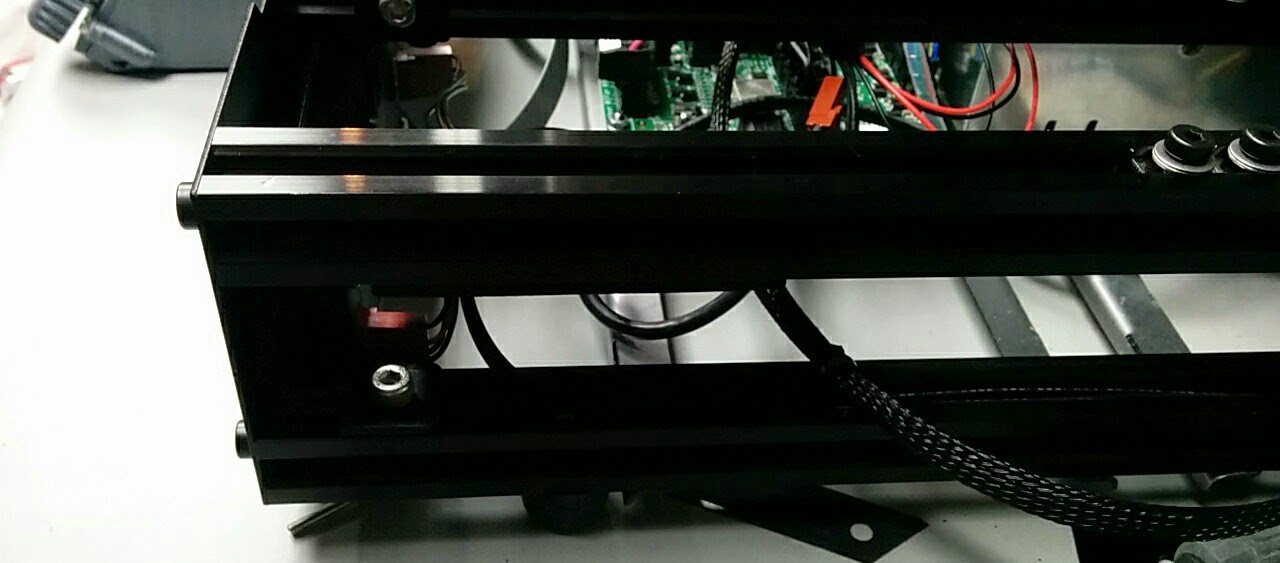
This shows the mounting screw which holds the mount on the bottom right extrusion:
And this shows the “flag” mounted. The box on the right holds the buck converter and the arduino which drives the LEDs (and came from the MTW optional prints folder).
You can find the STL and FreeCAD files here.