MendelMax3 - Z Stepper Mount Flex
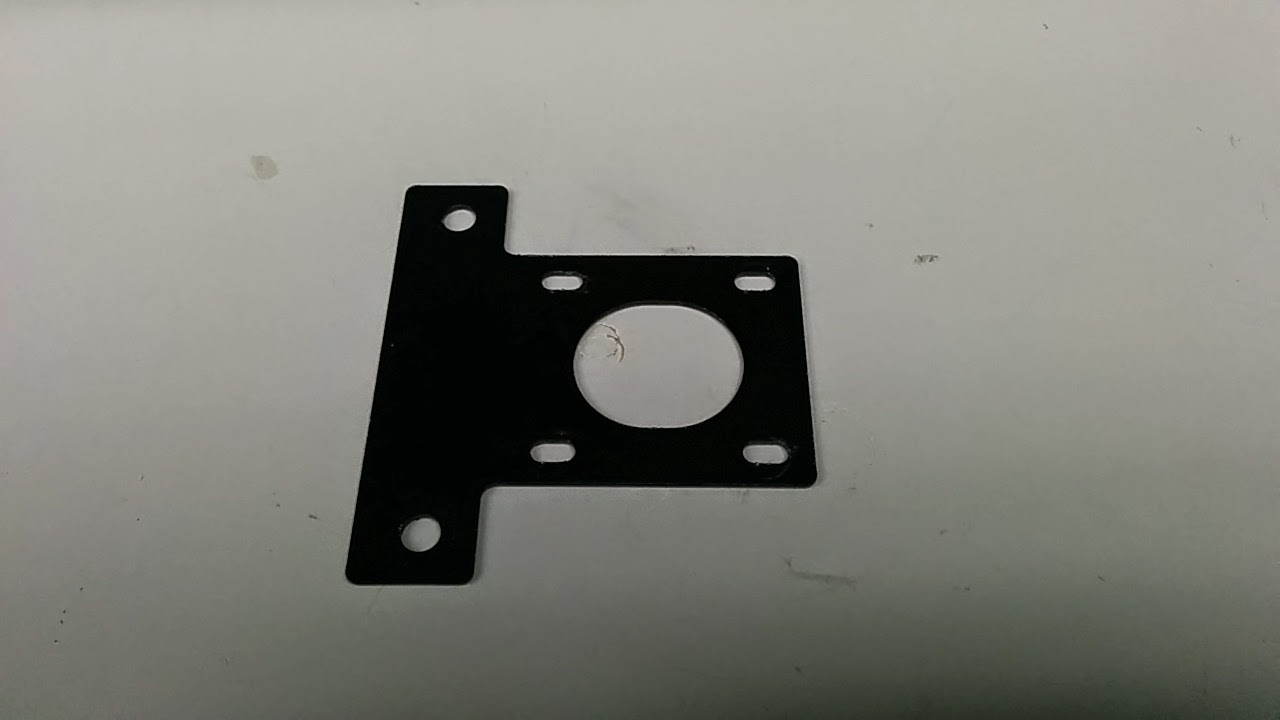
I suspected that there might be some flex in the Z stepper mount on my MendelMax 3 given that it’s a fairly thin piece of metal (0.050” or 1.3mm powdercoated stainless steel):
The first step was to see just how much deflection that existed. So I set up a dial test indicator on the outside of the stepper mount, moved the gantry down a bunch of steps, zeroed out the dial indicator and then started to move up in increments of 0.1mm. I had a big ole chunk of steel that I rested on back portion of the MM3, and used that to hold the magnetic base that held the indicator:
Wow 0.09mm of deflection, mostly in the first 3-4 layers.
My gantry is setup with 2 direct drive extruders, which means that there is a fair amount of weight being moved up and down on the Z axis.
From what I had heard, the MM2 used thicker aluminium parts. I also discovered that OpenBuildsPartStore sold a NEMA 17 stepper mount that could be adapted to work. It appears to be 0.125” (3.16mm) aluminum:
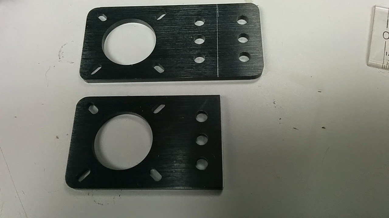
I used an X-acto knife to score a line 20mm from the edge, cut along the line using a hacksaw (ok - not really - I used my metal bandsaw, but this could easily be cut with a hacksaw) and cleaned up the cut edge with a file. For mounting, I lined up one edge with the 2040 vertical extrusion, and squared with the frame:
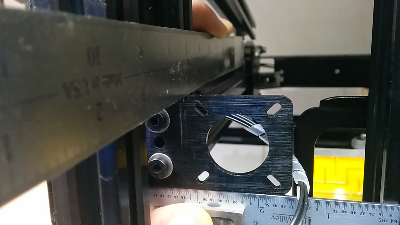
I then repeated the same test using the OpenBuild stepper mount:
Much better, only 0.03mm deflection. I think that having some type of braced mount, using a printed part (either by itself or as a reinforcement to one of metal mounts), would yield even less deflection. I’ll be following up with another bog post in the future once I get a chance to try that out.
Make sure you read Part 2 where MTW addressed the problem with some braces.