OX Build - Part 3
After getting things together up to the end of Part 2, I think that things should be assembled in a slightly different order.
Related: Unboxing, Part 1, Part 2, Part 3, Part 4, Part 5, Part 6, Clamps
I didn’t tighten the screws down on my delrin nut because I wanted to do it with the leadscrew installed. I found working on the Z axis to be alot more difficult than it needed to be, just because it was mounted on the gantry.
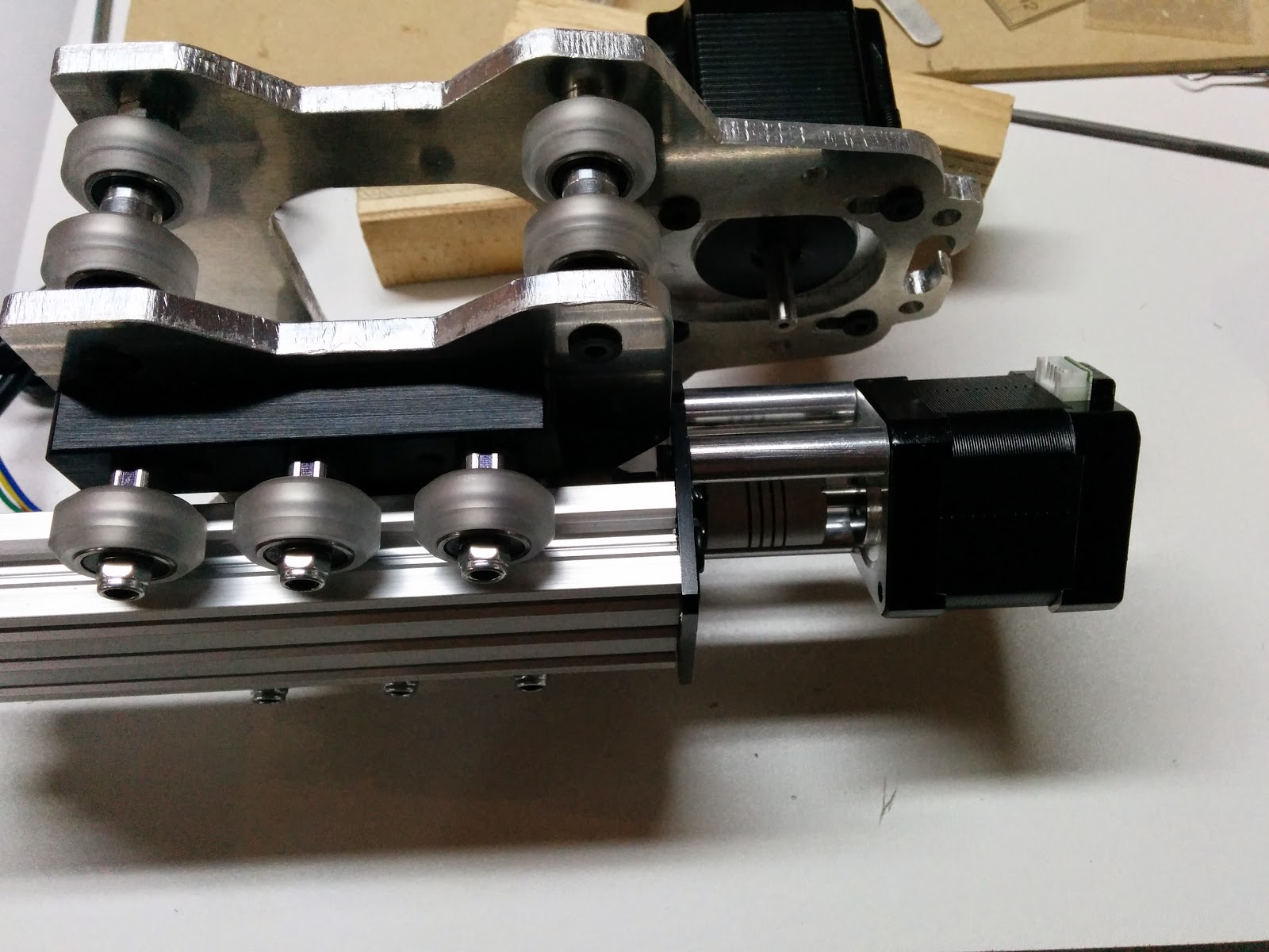
So I think that the entire Z axis assembly should be assembled first, then mounted on the gantry extrusions and screw the whole thing down.
I had issues getting my leadscrew to go through the delrin nut. I could start it, but couldn’t seem to get it to go all the way through. Looking into the nut I could see pieces of swarf still floating around:
I removed what swarf I could see with a pair of tweezers. Then I was able to get the leadscrew through, and a bunch more swarf came out:
I then ran the leadscrew through several more times. This is a shot of what came out (not including the bigger pieces I pulled out with the tweezers:

Remove the delrin nut and put it on the leadscrew. You’ll need to install the upper bearing and the locking collar first. Leave the 3 screws which mount the plate stepper plate to the extrusion slightly loose. Leave the 2 nylock nuts in the delrin nut (they should be on the side facing the extrusion).

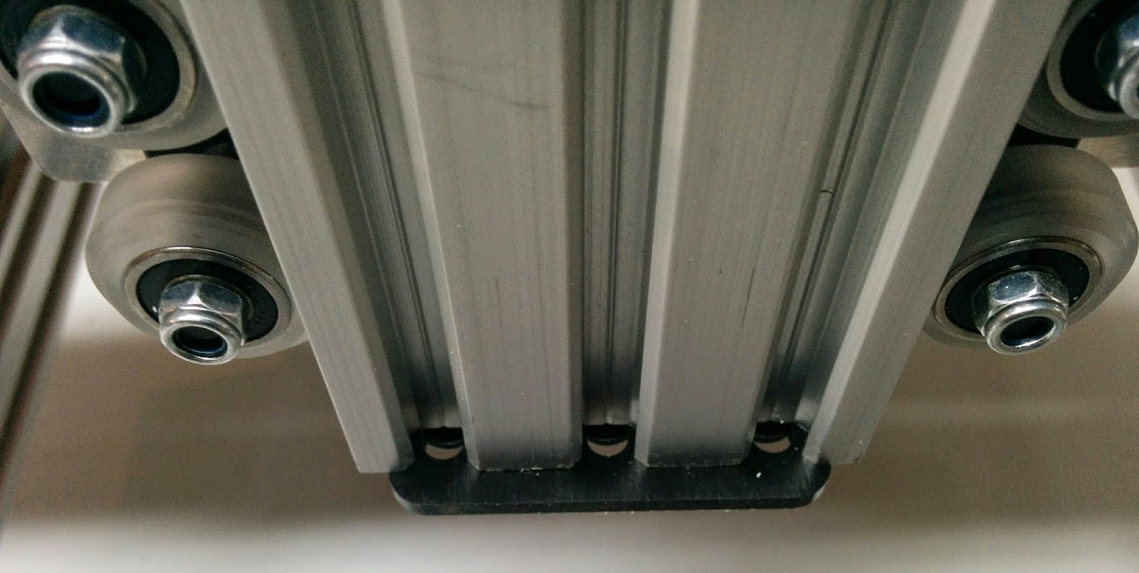
Slide the extrusion into place:
Line up the holes and put the leadscrew nuts in place. Tighten them up almost all the way, but leave them just a wee bit loose.

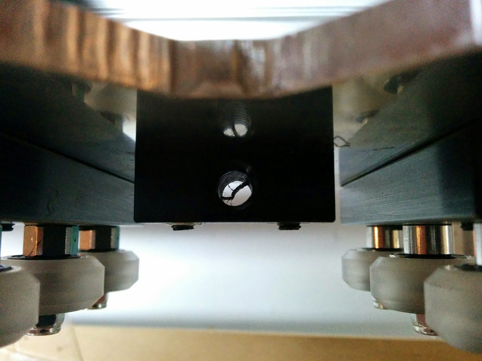
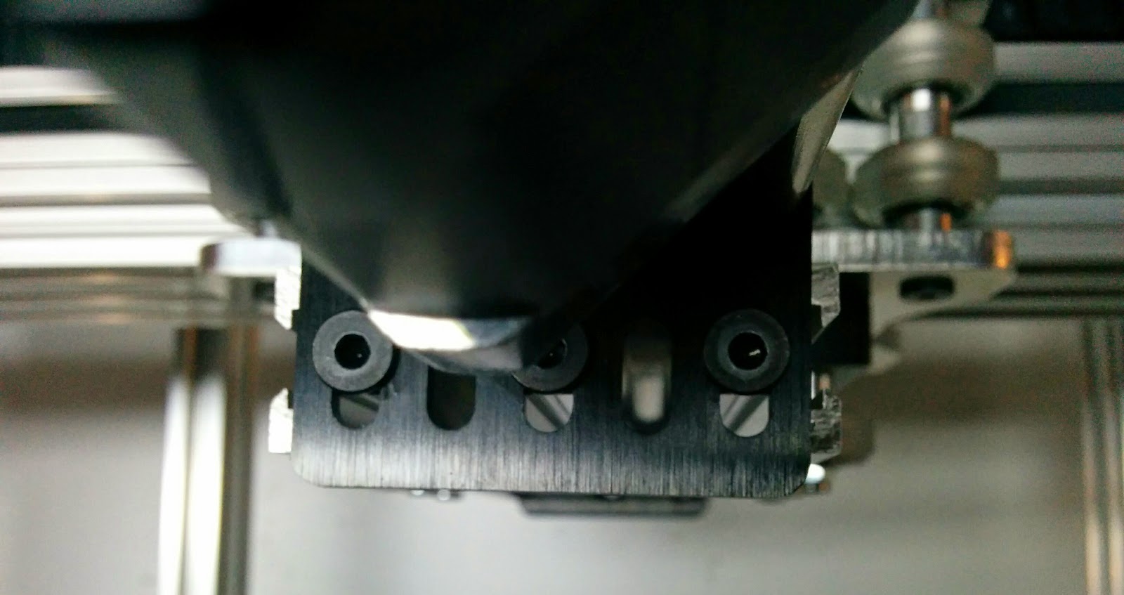
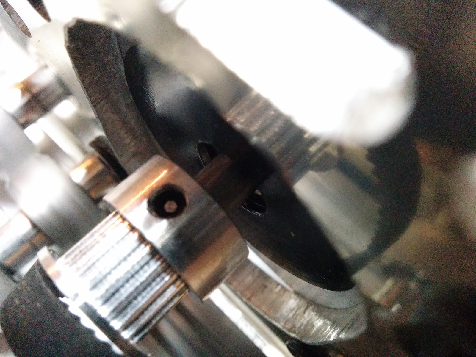
Now turn the leadscrew so that the extrusion is as close to the stepper end a possible, without actually touching the black mounting plate. Tighten up the screws on the mounting plate, taking care to keep the straight edge of the black plate parallel to the face of the extrusion. You’re also looking to have the leadscrew parallel with the back of the extrusion. This is the black edge I was talking about:
I found that looking through the holes between the mounting screws, you’ll be able to see part of the extrusion. In my photo below, none of the extrusion was visible.
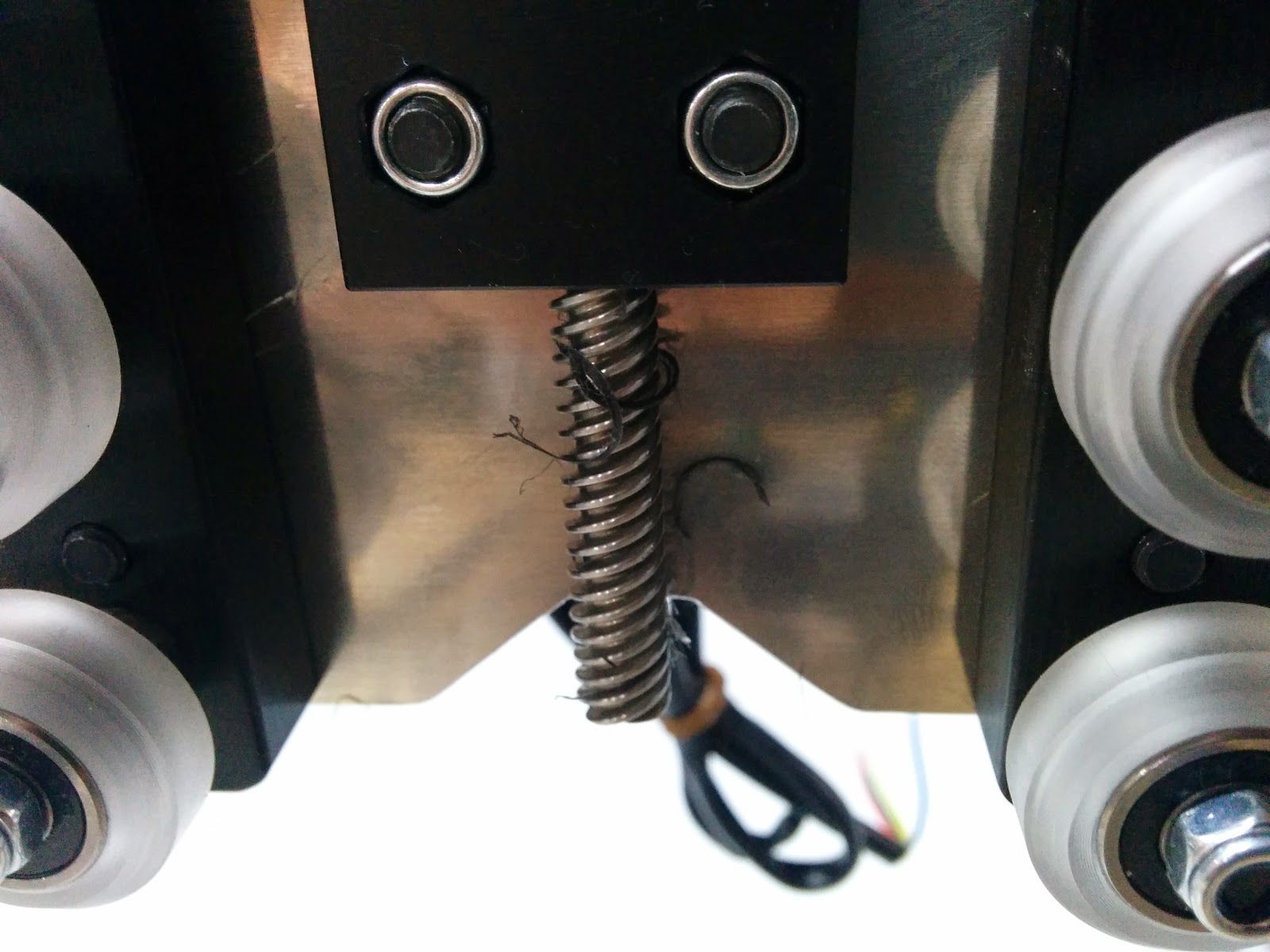
Now put the bottom black plate on and move the extrusion up (by rotating the leadscrew) until the bottom plate is almost touching the front plate, and tighten up the screws.
Make sure that the bearings fit into the recess in the black plate, and secure the lock collar. Make sure that they is no play between the lock collars and the bearings.
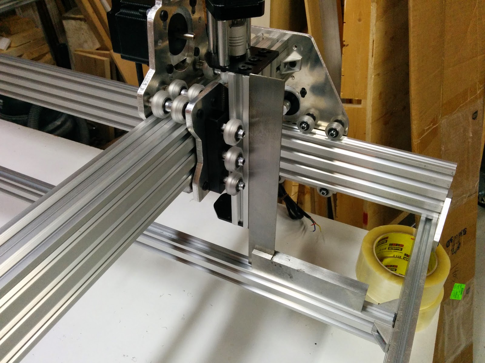
Now you can remount the z axis assembly on the extrusions and mount the extrusions.
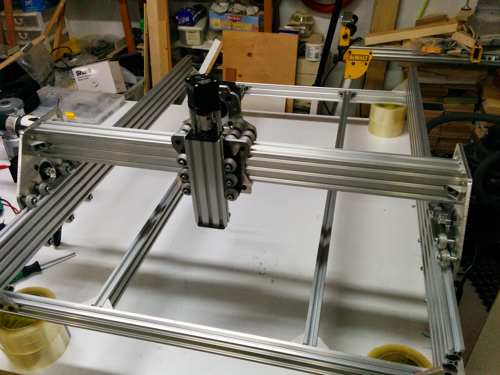
I verified that the front of the z-axis was sqaure with the bed while tightening the screws up.
Time for the belts. I filed the ridges off the edges of the bolts that were going to be used to securing the belts. With the ridges things tend to move as the screws are tightened.

I found the easiest way to hold the screws while filing the ends was to put the screws in my allen wrench and then hold the screw with my thumb and finger while my hand was wrapped around the allen wrench:

I also didn’t like the screws clamping directly on the belts. I had some Simpson Strong Tie metal plates that were about 0.036” or 0.9mm thick).
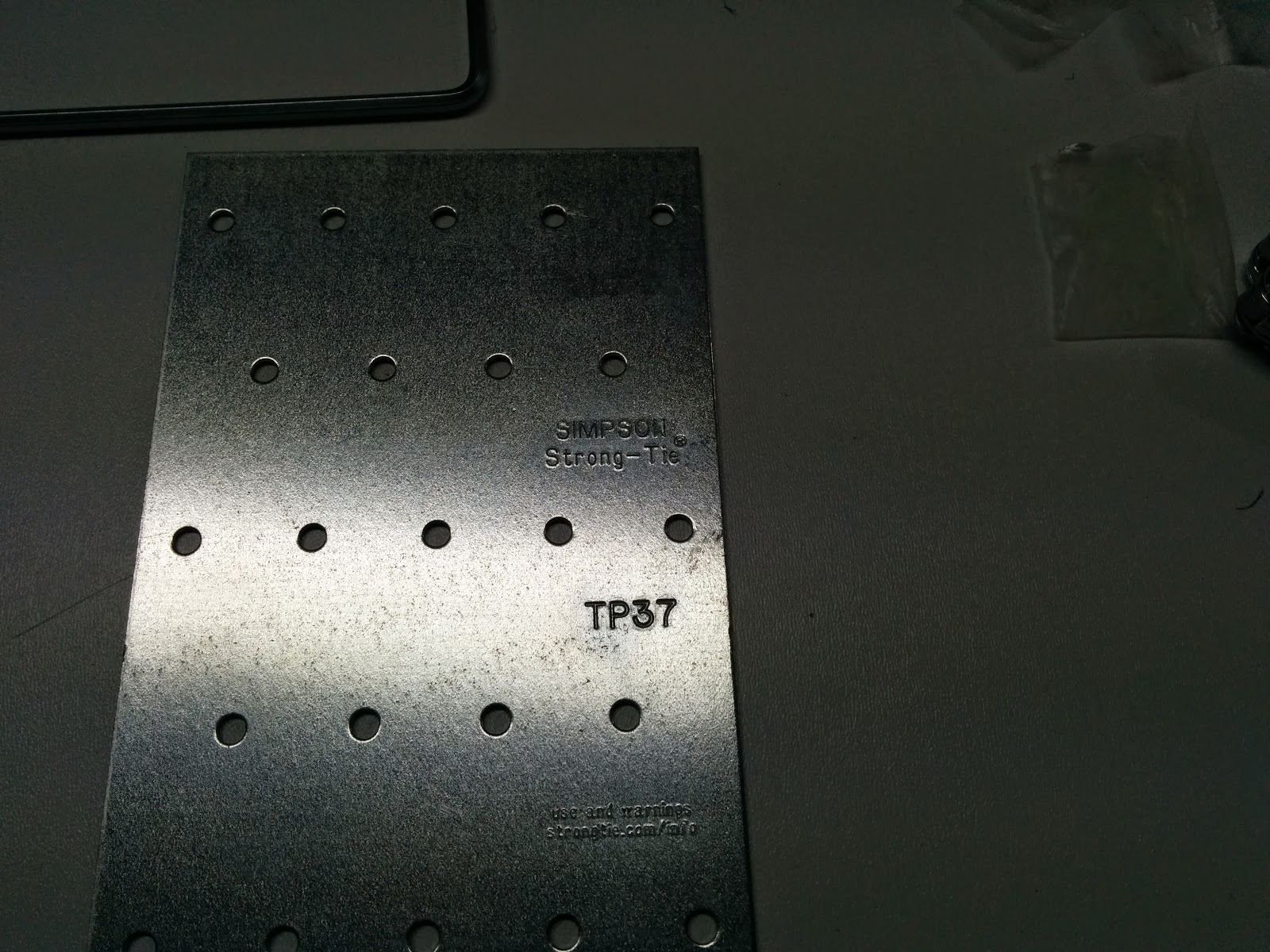
I cut a piece about 5mm wide and the same width of a T-nut.
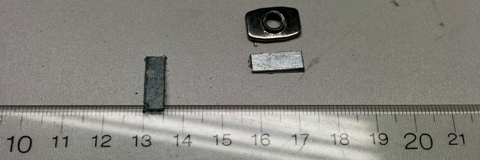
I put these between the T-nut and and the belt, so that the screw was clamping on the metal shim instead of directly on the belt.
The instructions use drop in nuts for the X axis belt, so I did that, but I think I would have preferred to use the regular T-nut and shims.
I’d like to put belt tensioners on all of the belts, so then this will be pretty much a moot point.
Tip: don’t use ball end allen wrenches for tightening up the grub screws.
I twisted one of mine right off. I could move it around but couldn’t get it out. Even gravity wasn’t being helpful. Then I tried a stack of rare earth magnets and they pulled it right out (phew):

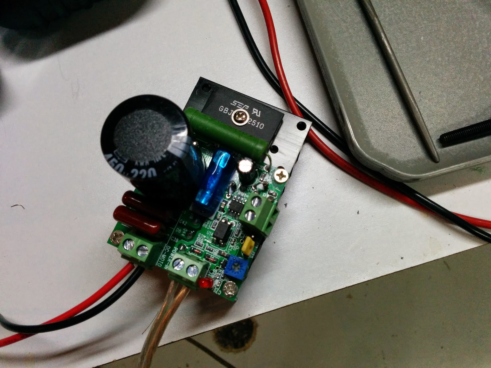
Brandon (from Hobby-Fab) asked me to check my speed controller (since he was going to be sending me replacement bearings - apparently somebody else had a speed controller that went bad.
I wired everything up:
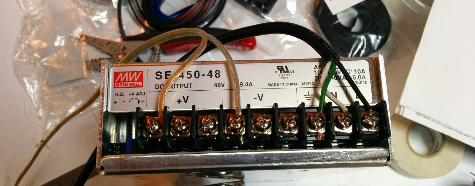
And pluugged it in. The spindle would start turning and immediately stop. The power supply seemed to be cutting out.
Doh:

I had checked the 24V supply when I unpacked everything but neglected to check the 48V supply, and it was set to 230V.
I changed it to 115V:
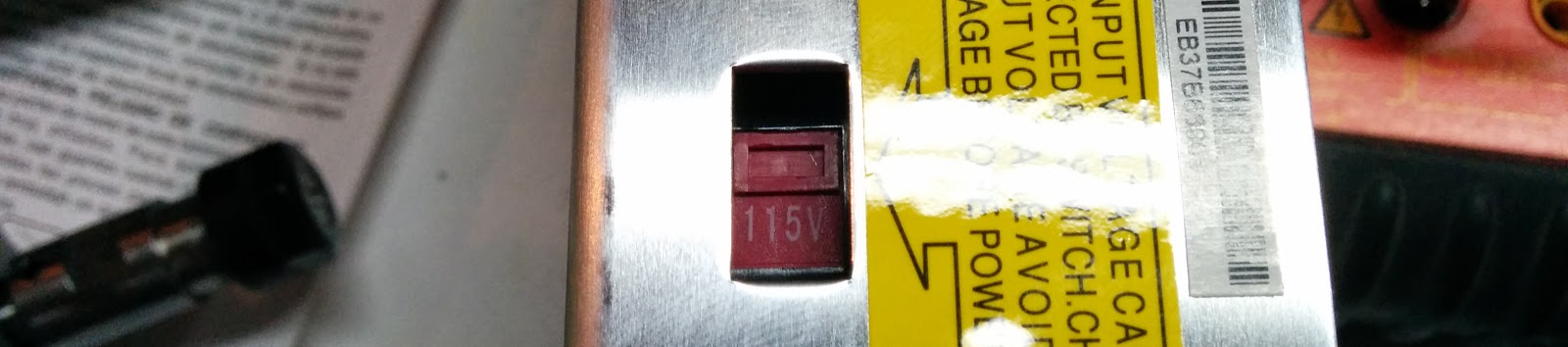
and lo and behold, it worked!
I took a video of the Quiet Cut spindle:
And also from my Bosch 1619EV router that I use for normal woodworking:
That’s it for this part. Next will be the wiring.
Related: Unboxing, Part 1, Part 2, Part 3, Part 4, Part 5, Part 6, Clamps