OX - CNC Router - unboxing
Woot. My OX CNC Router Kit showed up today. I ordered this from SMW3D (now Hobby-Fab).
Related: Unboxing, Part 1, Part 2, Part 3, Part 4, Part 5, Part 6, Clamps
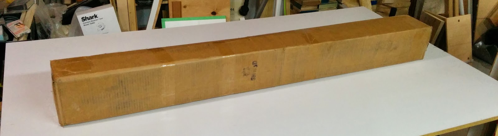
I ordered the 1000mm x 750mm version. The box was 6” x 6” x 60” and weighed about 37 lbs.
And here we have the contents of the box. I like the use of the 90 degree carboard angle pieces on the corners.
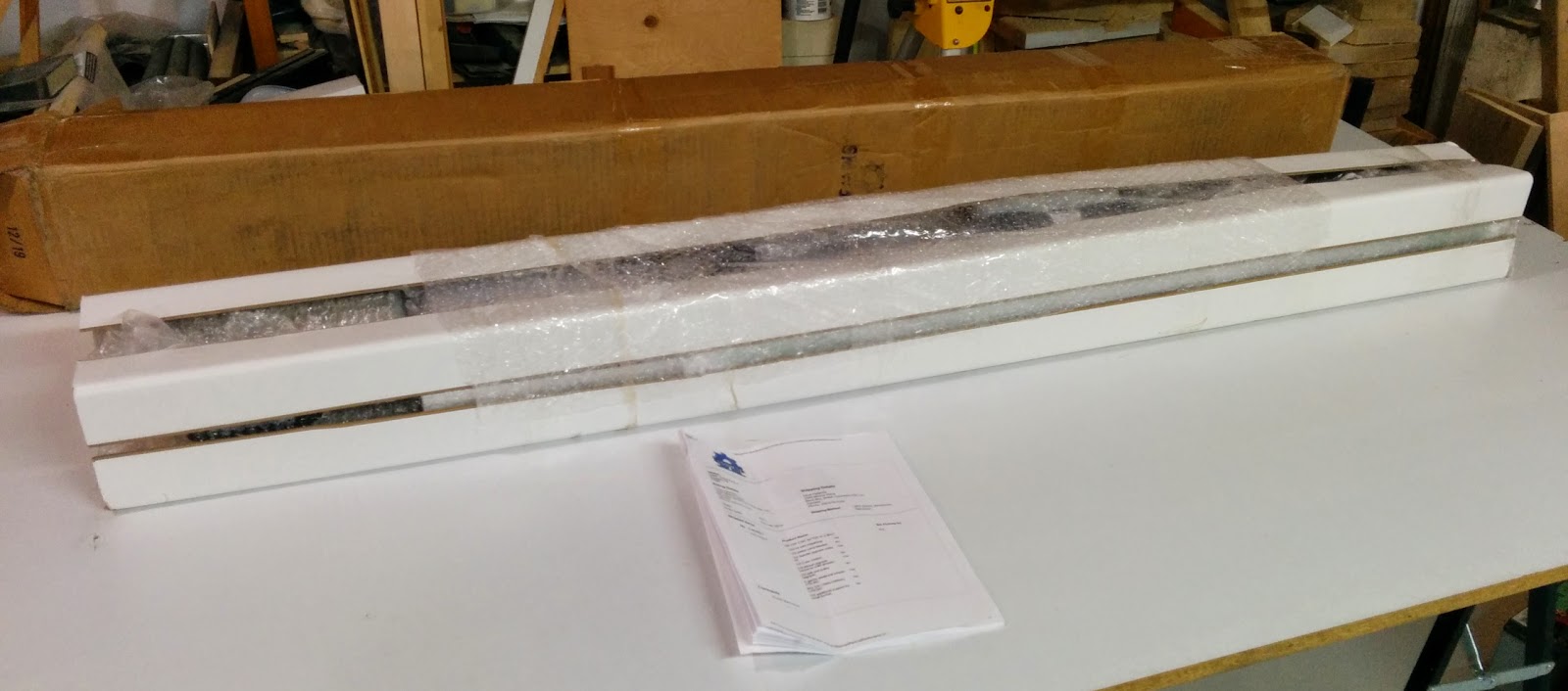
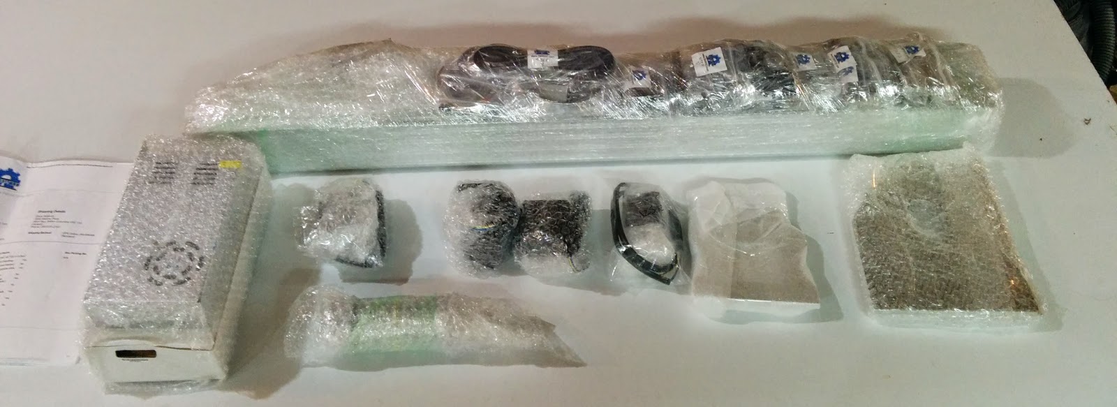
After removing the first layer of wrapping and the cardboard 90’s.
I opened up the power supplies. The first one is a 24V supply for the controller (not included) and for driving the steppers. I ordered a TinyG controller which coincidentally showed up today as well.
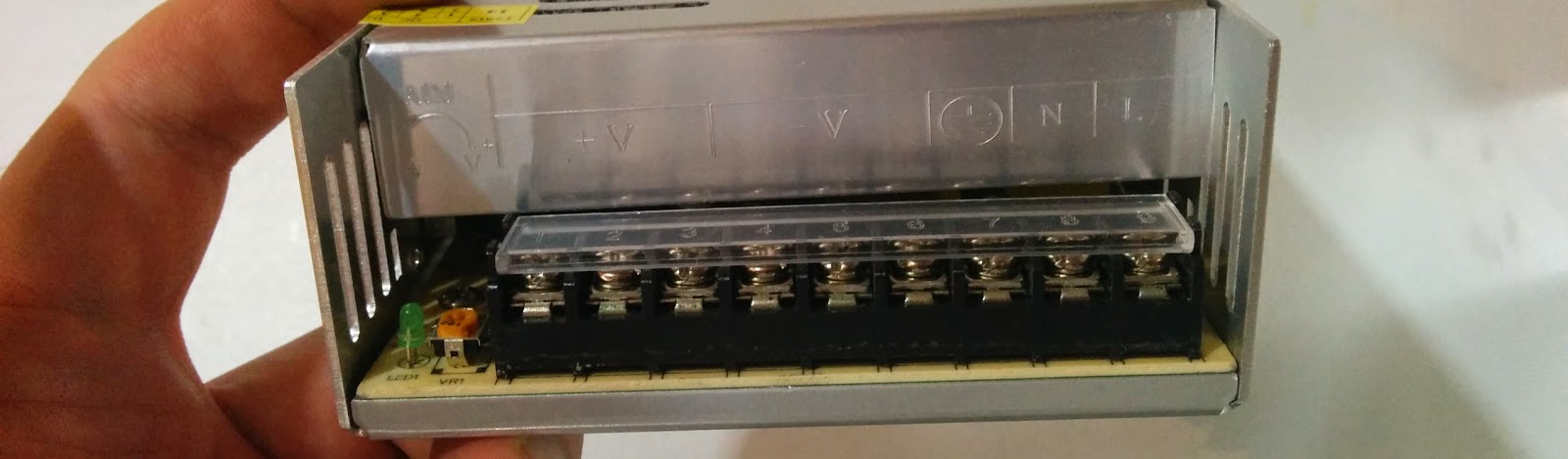

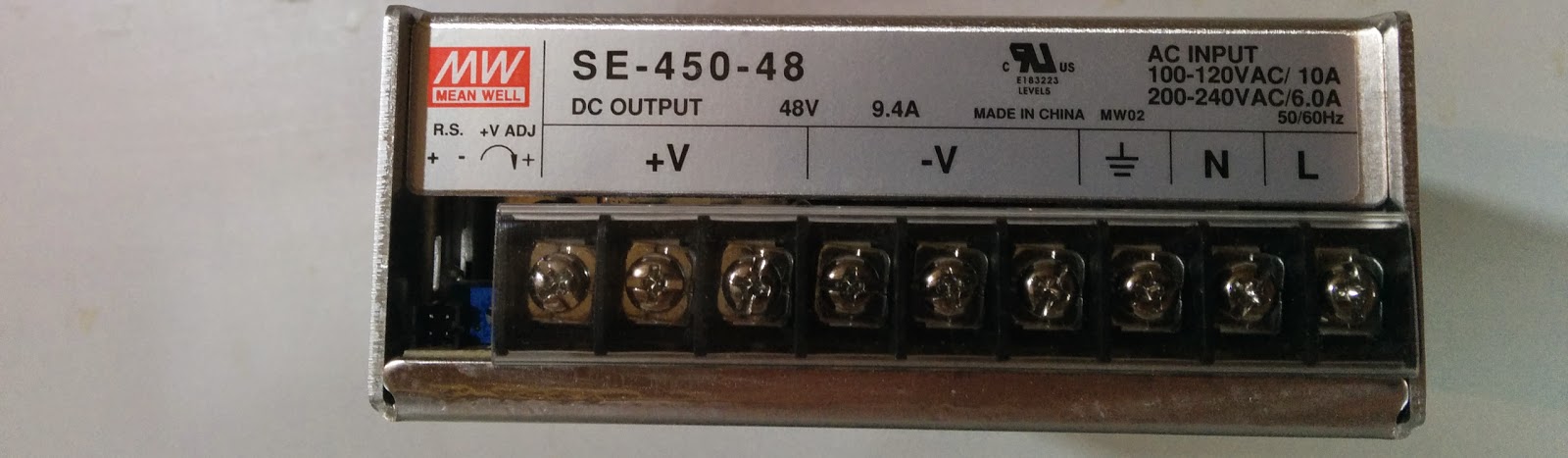
The second power supply is a 48V supply for the 400 wattt spindle.
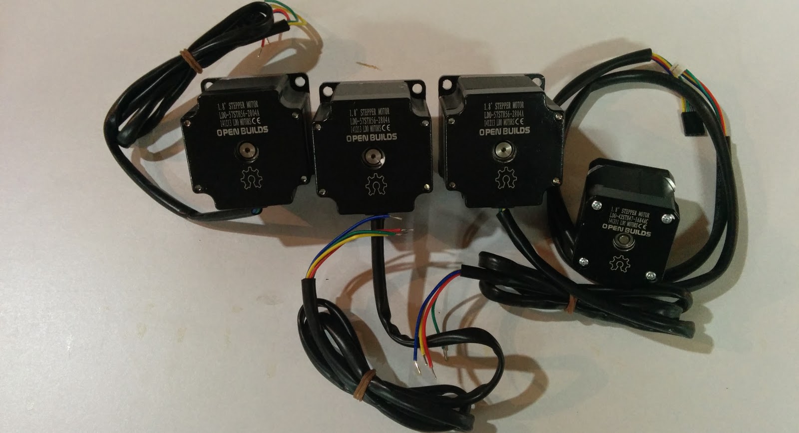
4 stepper motors, 2 NEMA 23’s for the Y axis, 1 NEMA 23 for the X axis, and a NEMA 17 for the Z axis.
Closeup of one of the NEMA 23 steppers. These are 175 oz-in, 2.8A steppers.
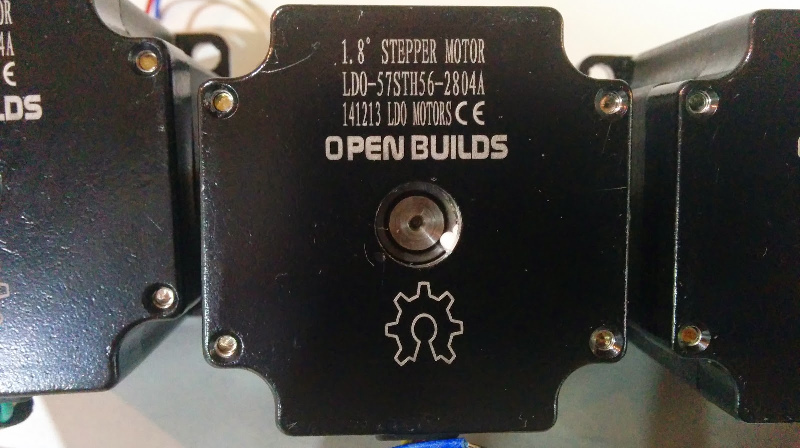
The wires for the NEMA 23 steppers are 22 AWG.

Closeup of the NEMA 17 stepper. This is a 76 oz-in 1.68A stepper.
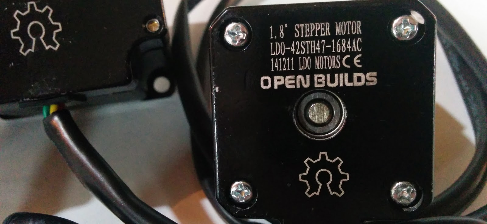
The NEMA 17 has a plugin connector on it:
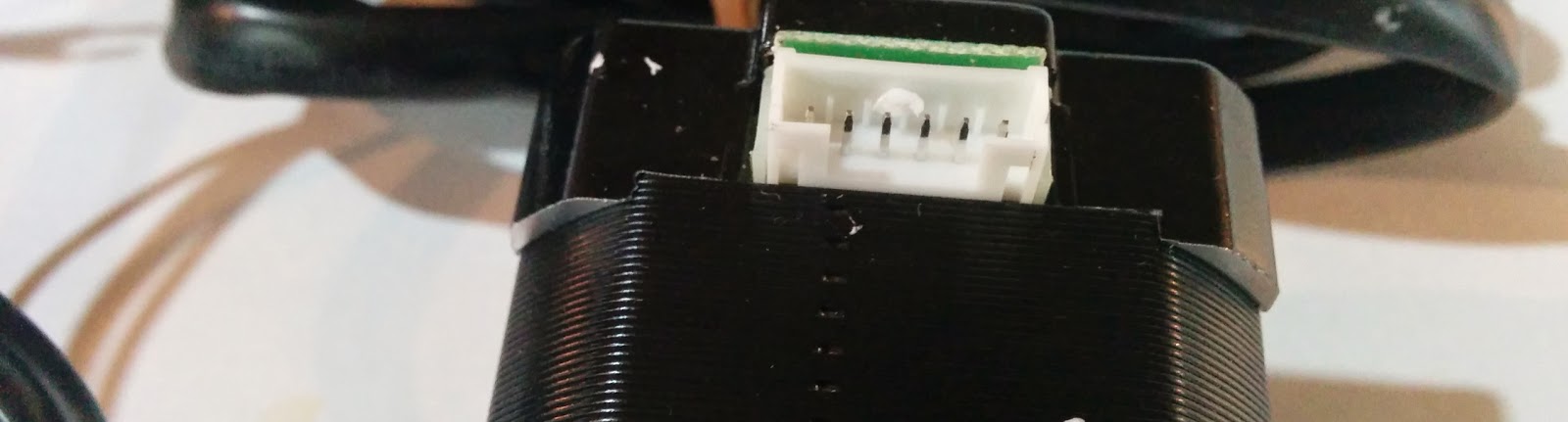
The wires for the NEMA 17 were 24 AWG:

The 400W spindle. The top part appears to be a fan and rotates with the spindle.
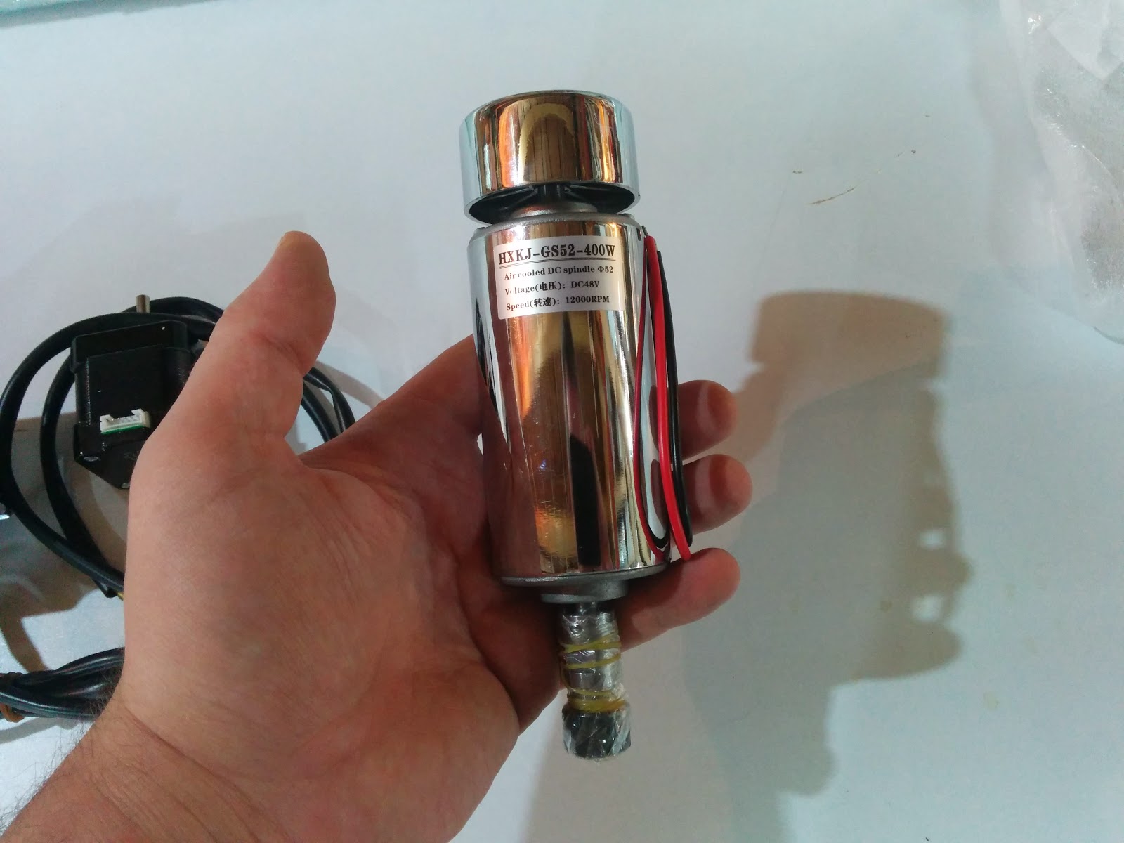
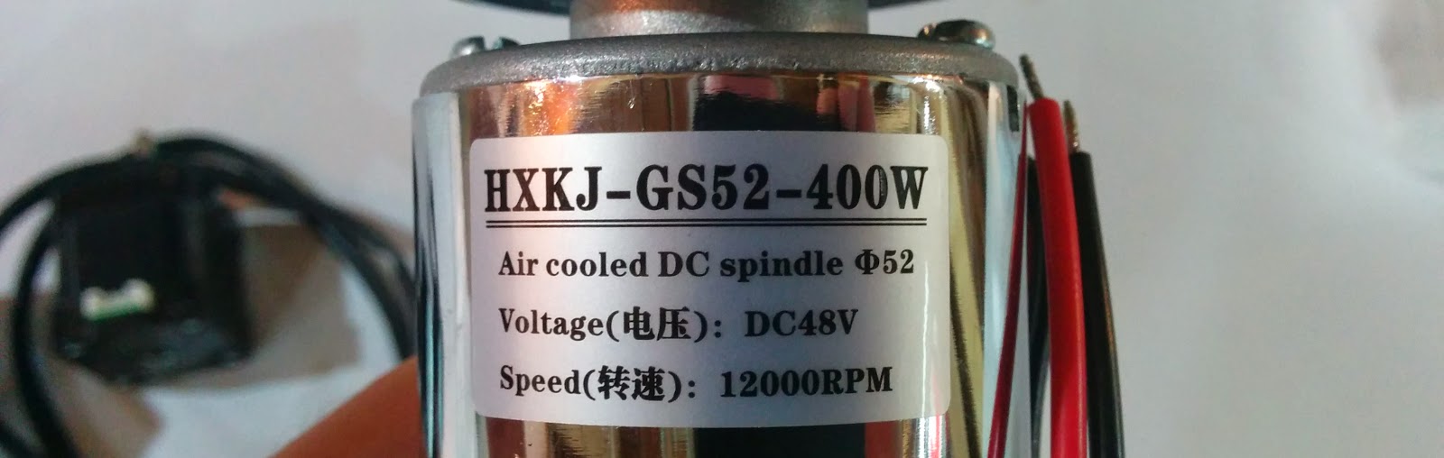
Closeup of the nameplate:
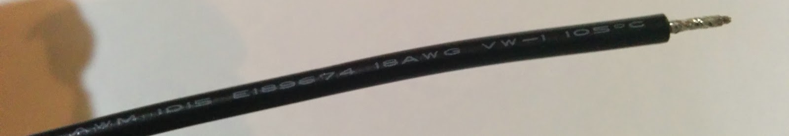
The wires for the spindle are 18 AWG:
And the business end uses an ER11-A collet, and came with a 1/8” collet.

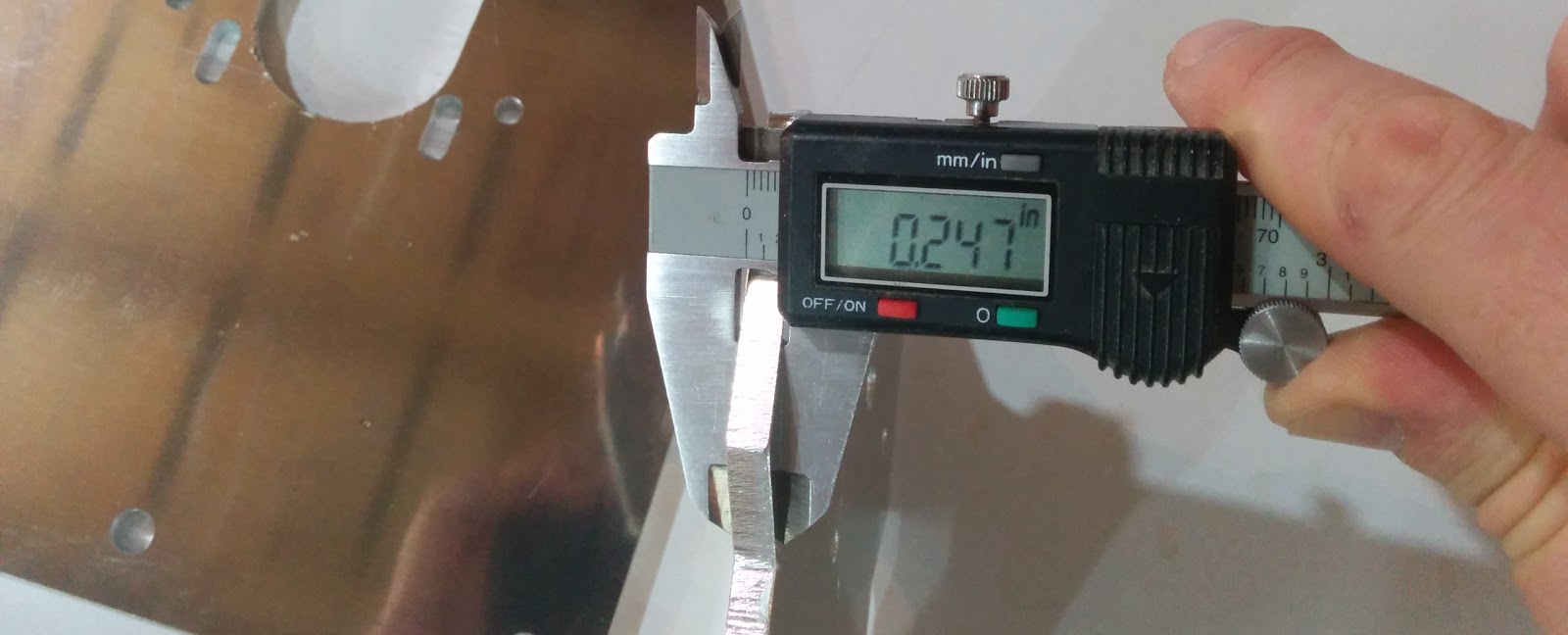
Next up were the plates.
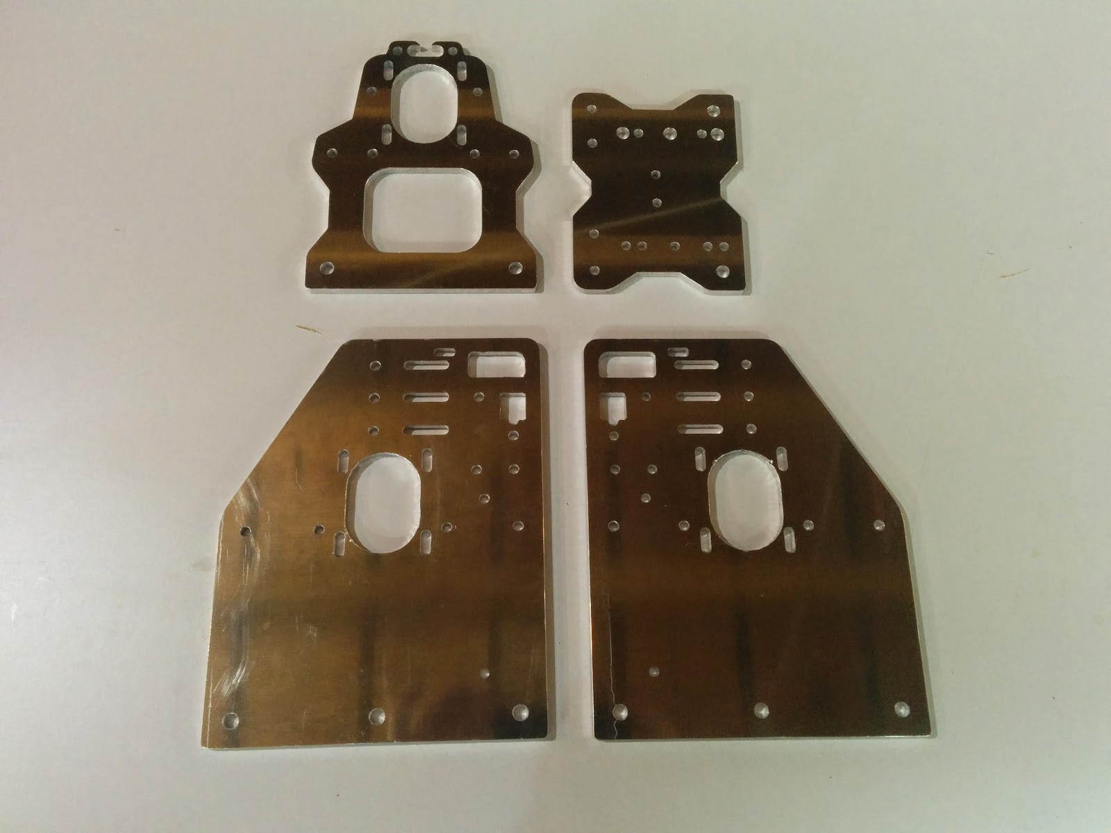
These were cut from 1/4” aluminum.
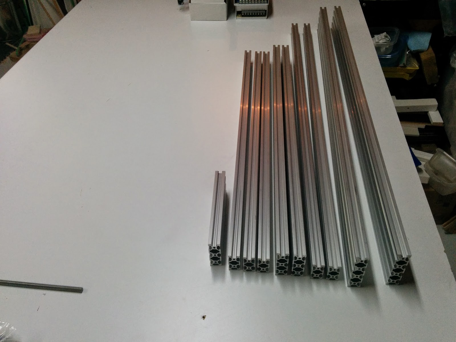
Here we have all of the extrusions:
The rest of the parts were labelled with the corresponding step from the manual. The speed controller is in the top right, and the leadscrew was hidden inside one of the hollow portions of one of the extrusions.
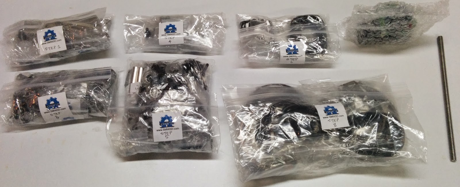
The step 1 bag includes pieces that go with some of the extrusions to put the frame together.
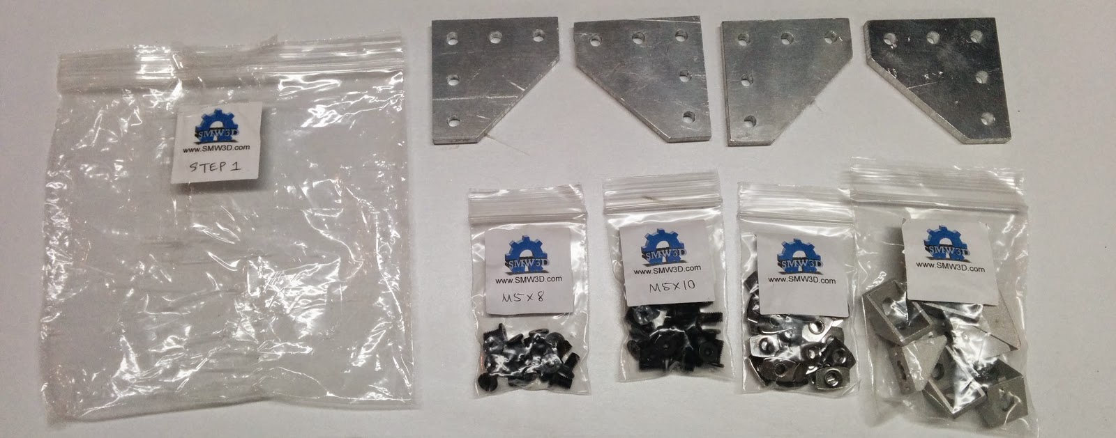
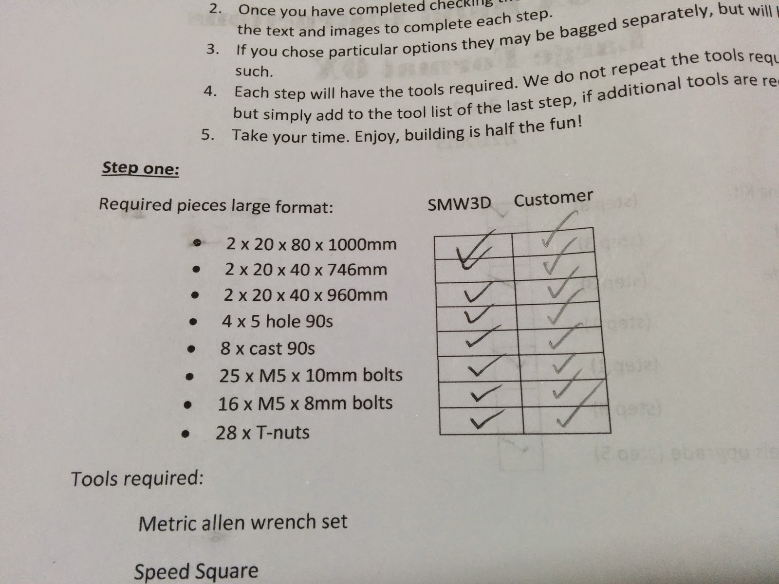
The manual includes a parts list for each step, and a place to tick off and verify that all of the parts were included:
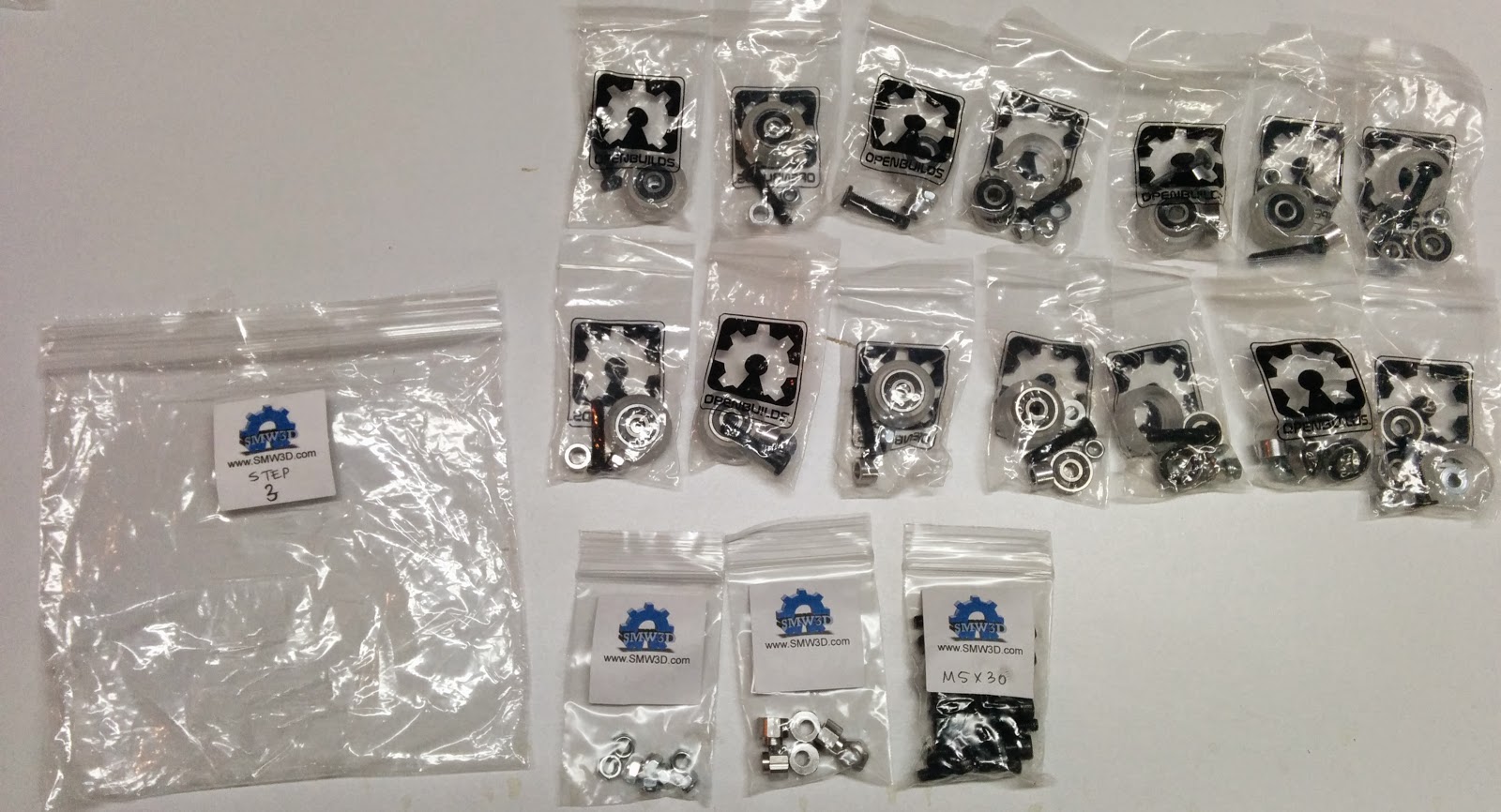
The step 3 bag has the parts for assembling the Y gantry pieces.
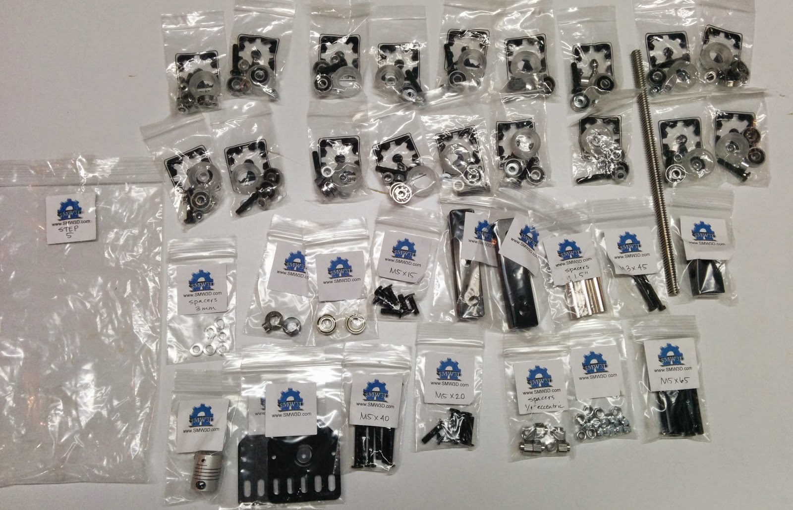
The step 5 bag has the pieces for assembling Z axis.
The step 6 bag has the belts and pieces for securing the belts.
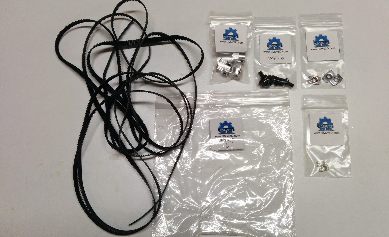
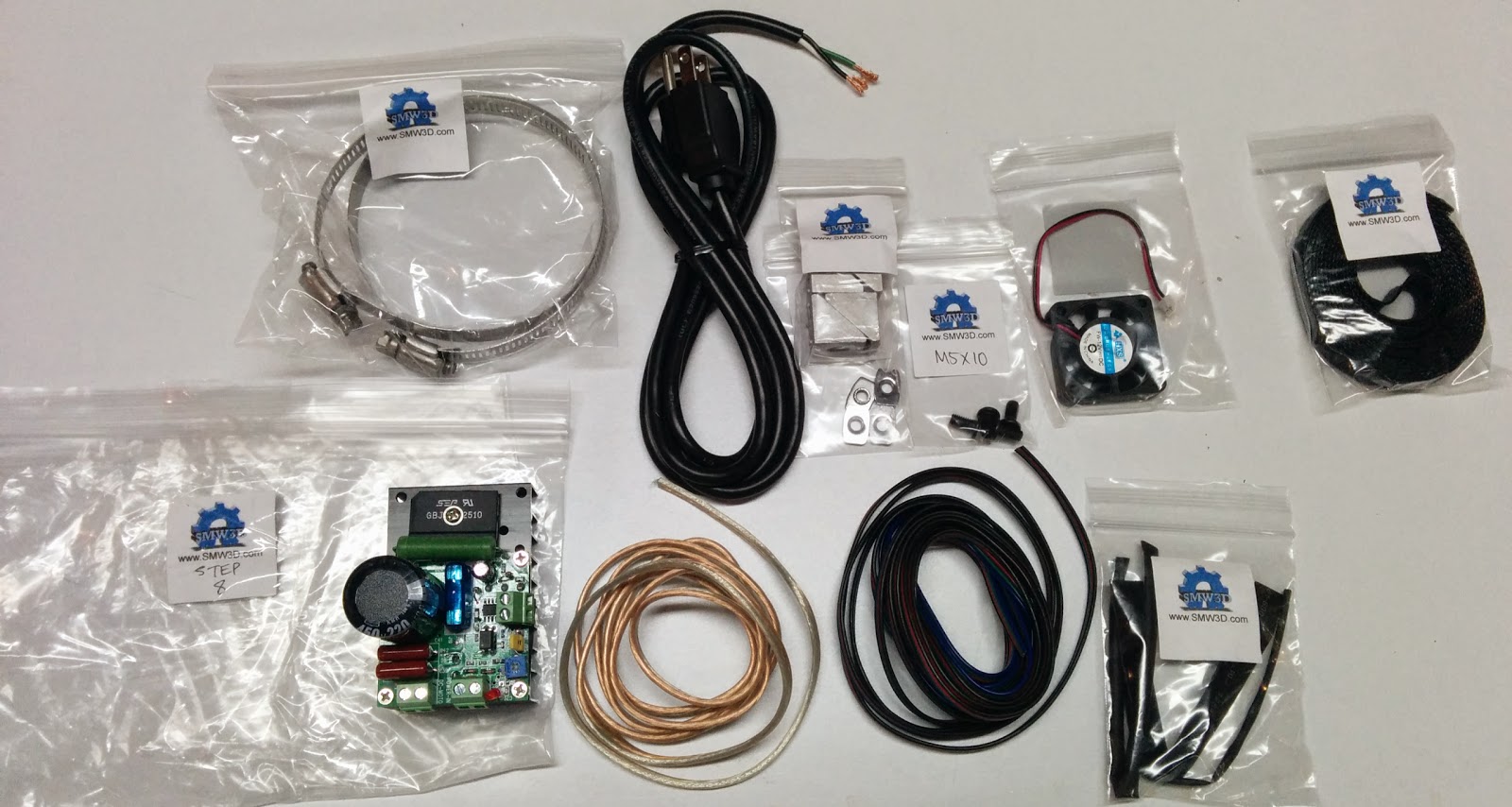
The step 8 bag has all of the wiring pieces and the hose clamps used for the spindle mount.
I also took some closeups of the spindle controller: This connector is for the leads which go to the spindle itself.
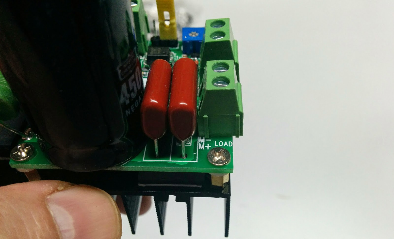
The connector next to that is for the power in:
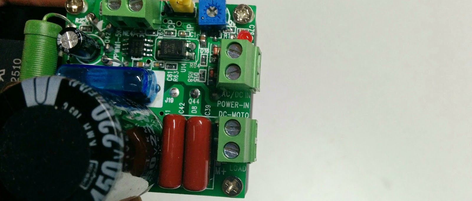
And the final connector is a PWM connector for controlling the speed:
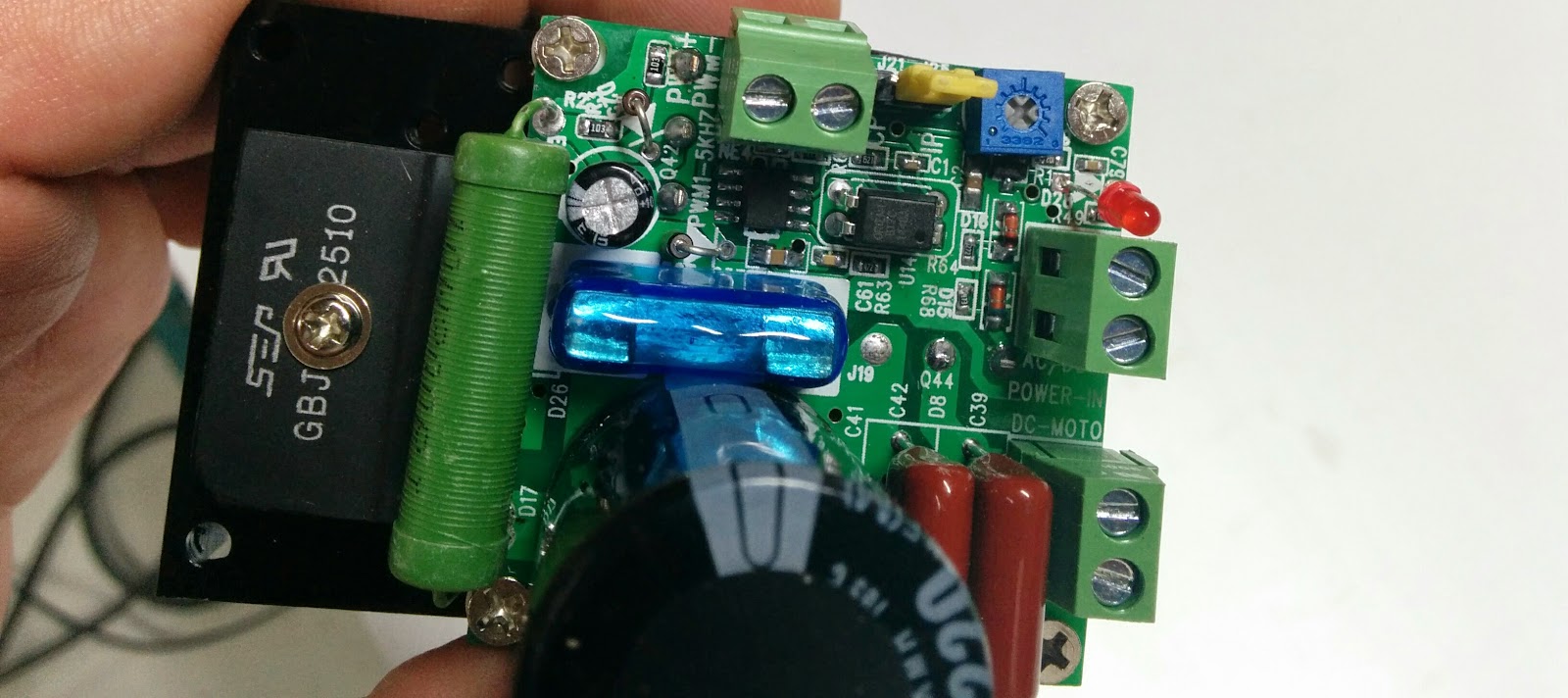
There is also a yellow jumper which has 2 positions which appear to be labelled CP and IP, along with a potentiometer (not sure what it does yet).

That’s it for the parts. Looks like a fairly straightforward build.
UPDATE: I found this document which describes a very similar speed controller. When the jumper is in the IP position, then the potentiometer controls the speed, and when the jumper is in the CP position, then the PWM input controls the speed. I also found a forum post on amazon which mentions that IP stands for “Internal Pulse width” and CP stands for “Computer Pulse width”.
Related: Unboxing, Part 1, Part 2, Part 3, Part 4, Part 5, Part 6, Clamps