OX Build - Part 1
Here are some photos and notes I took while starting my OX build.
Related: Unboxing, Part 1, Part 2, Part 3, Part 4, Part 5, Part 6, Clamps
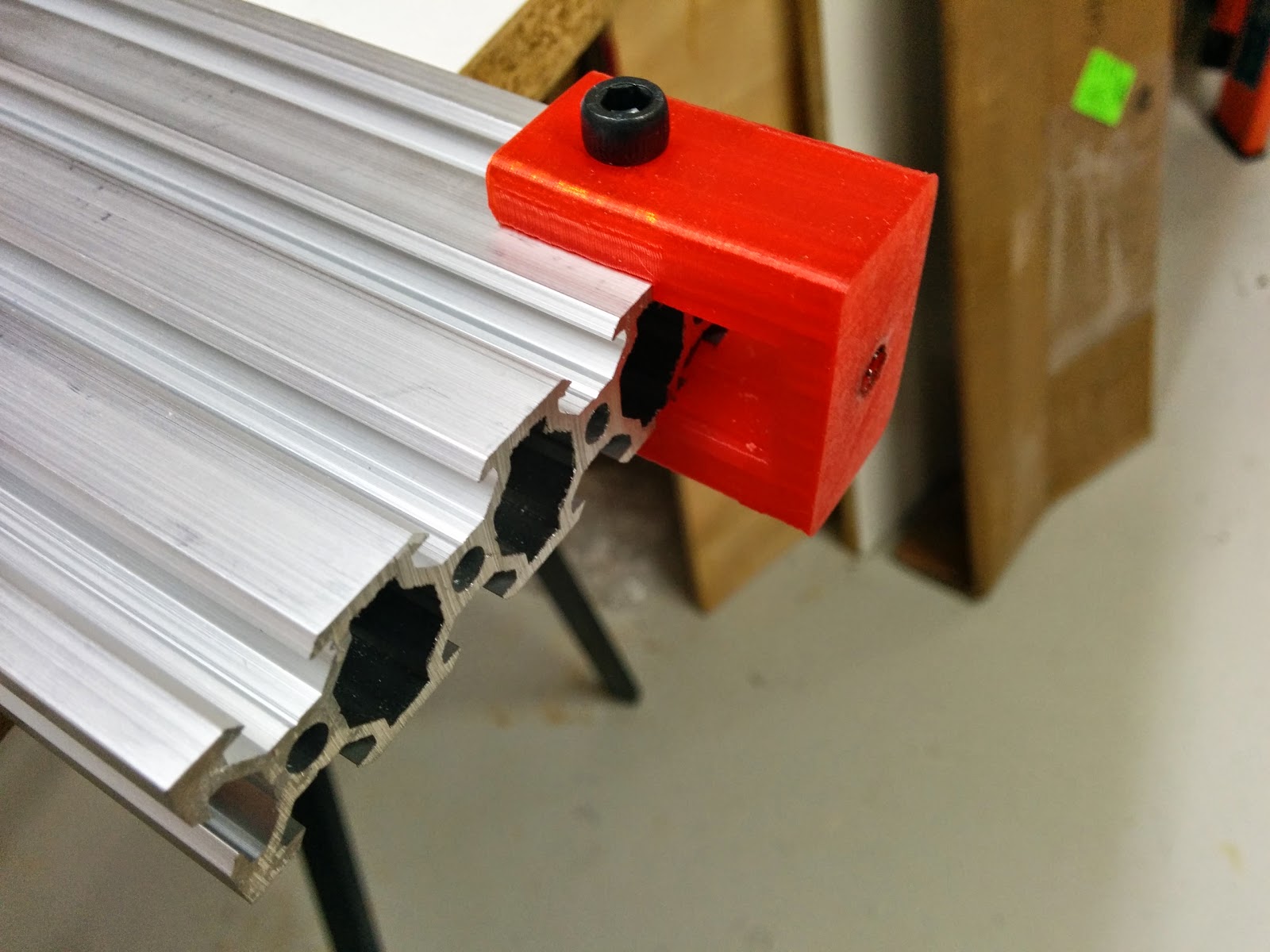
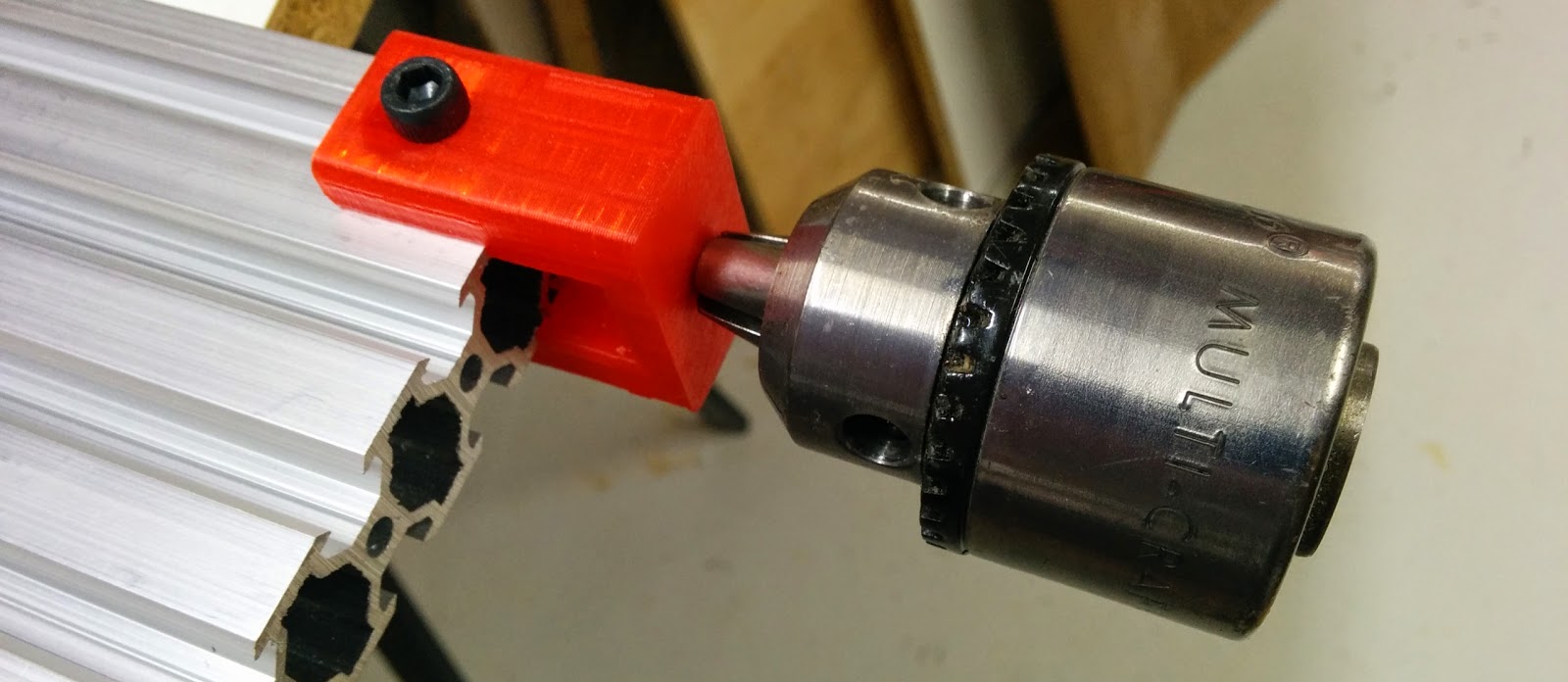
If you have access to a 3D printer, then this Tap Jig works really well for ensuring that the tap runs true.

This is how it mounts on the extrusion:
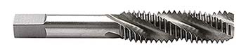
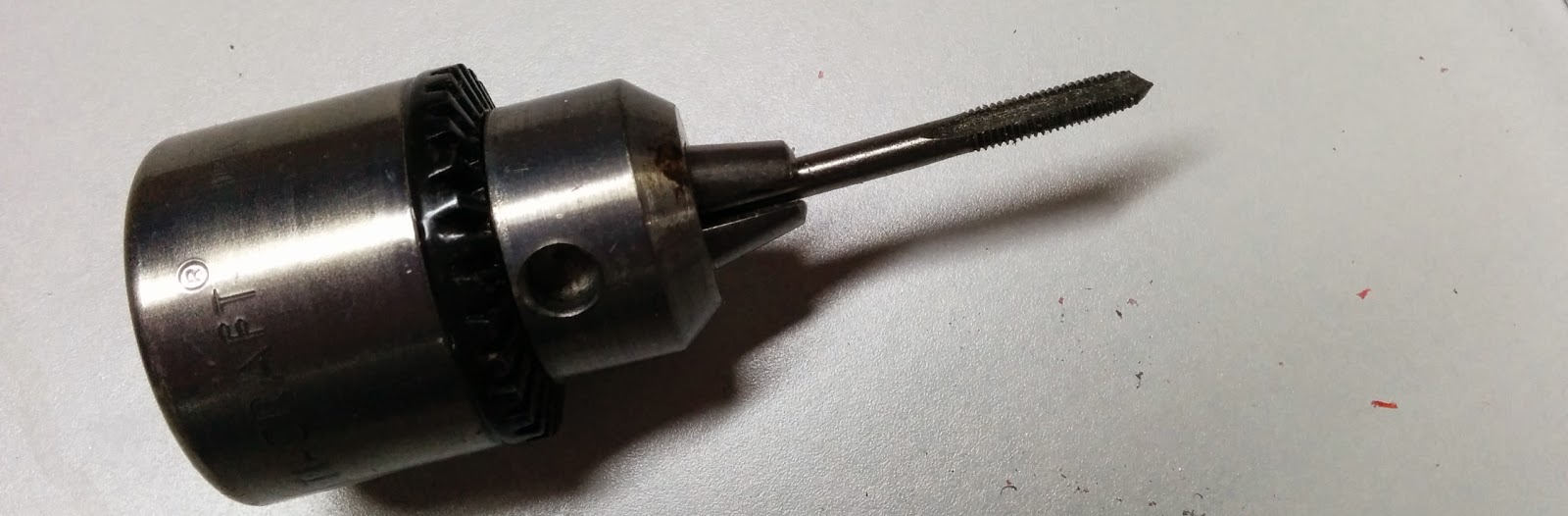
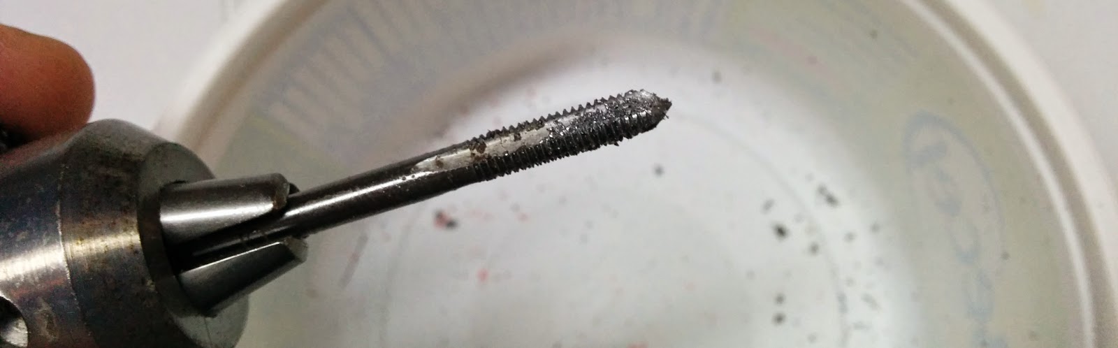
I don’t seem to have much luck using tap handles, and I’ve found that using a drill chuck works much better. You’ll need an M5x0.8 (metric coarse) tap. The one pictured below is the traditional tap. Spiral flute taps (which pull the chips out of the hole) or spiral point taps (which push the chips deeper in the hole) can be used without backing up, but the M5 spiral flute I bought had the wrong pitch (M5x0.5 which is call metric fine). So I had to use the tap from my metric tapping set which was neither spiral flute not spiral point.
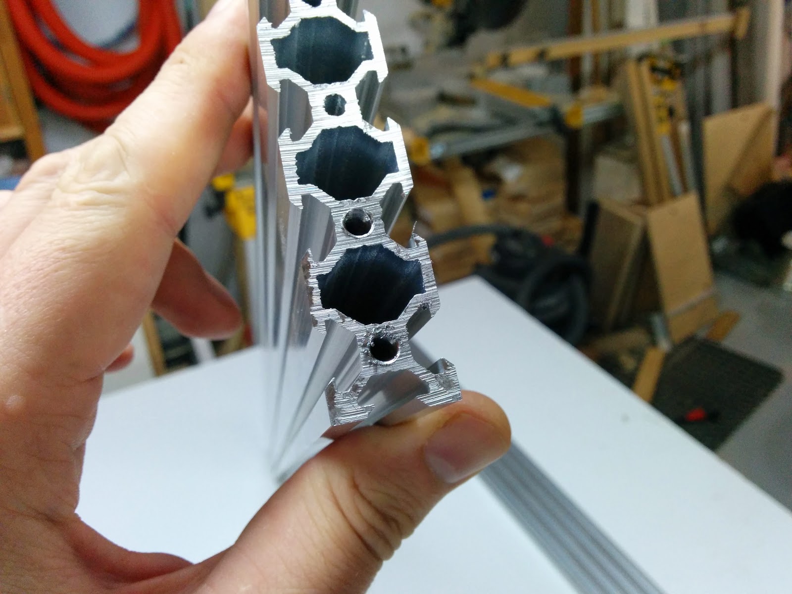
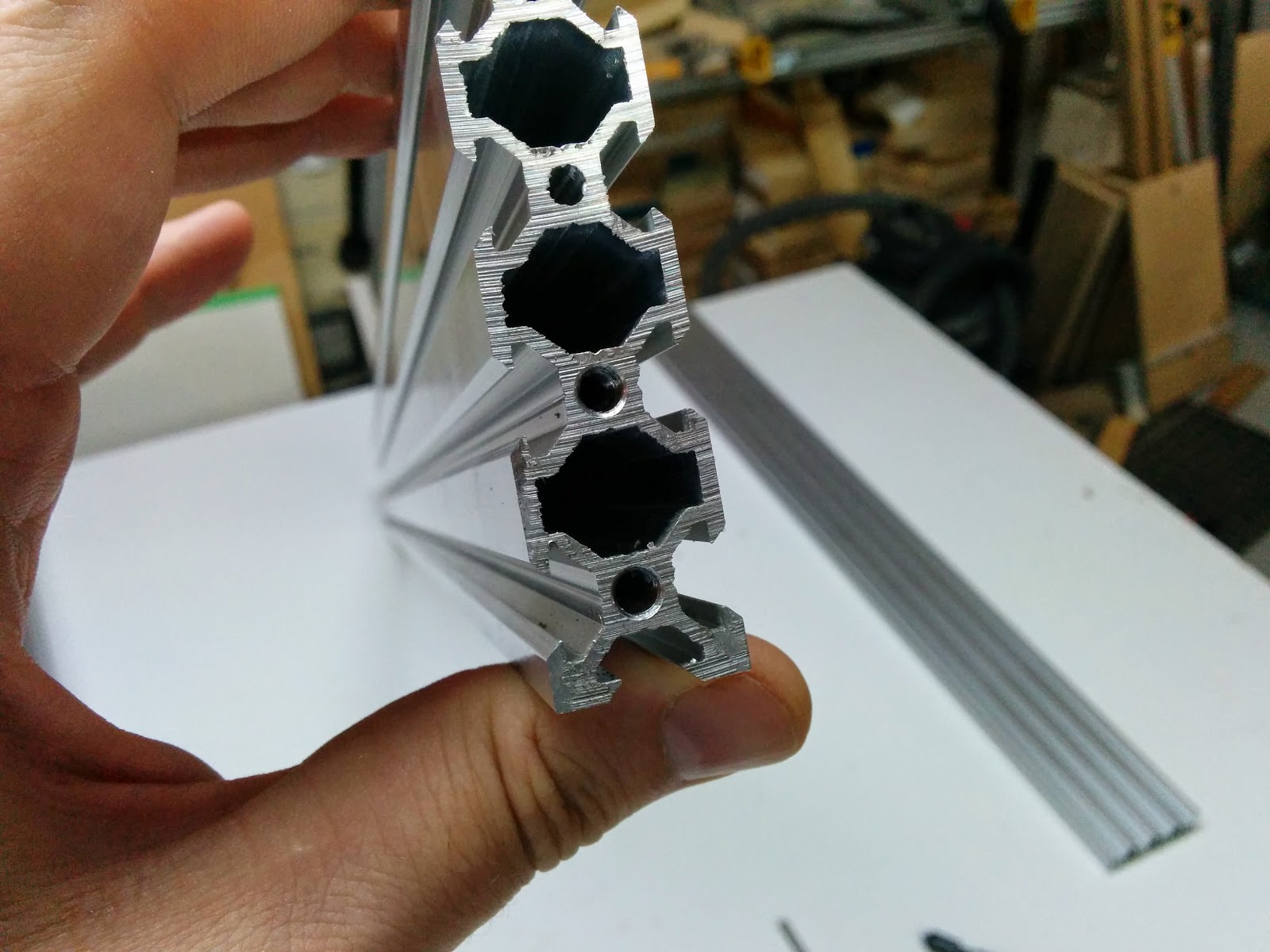
There is another type of tap, called a forming tap, which apparently produces stronger threads, and can also be driven without backing out. However, forming taps require a slightly larger starting hole. The holes in the center of the extrusion are right around 4.3mm which is the correct size for use with an M5 cutting tap.
With a traditional tap, i normally grab the drill chuck, twist it forward 1/2 turn (which is about as far as your wrist can twist), back up 1/4 turn or so, and move it back to the twisted position. Let go, untwist your hand grab the drill chuck again and repeat.
I use A9 cutting fluid:
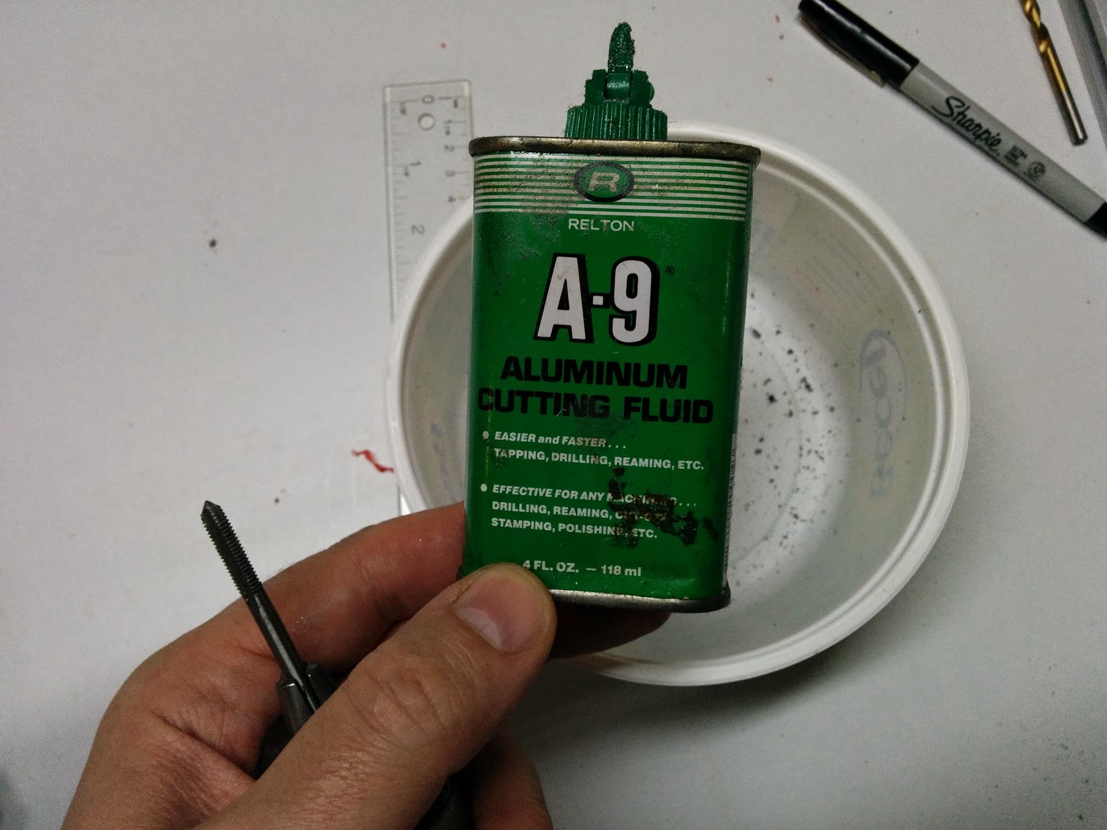
When hand tapping, if you notice that the force required to turn the tap suddenly increases, then you should back the tap all the way out and clear the flutes:
Otherwise, the swarf (technical term for the metal that gets cut away) can jam things up.
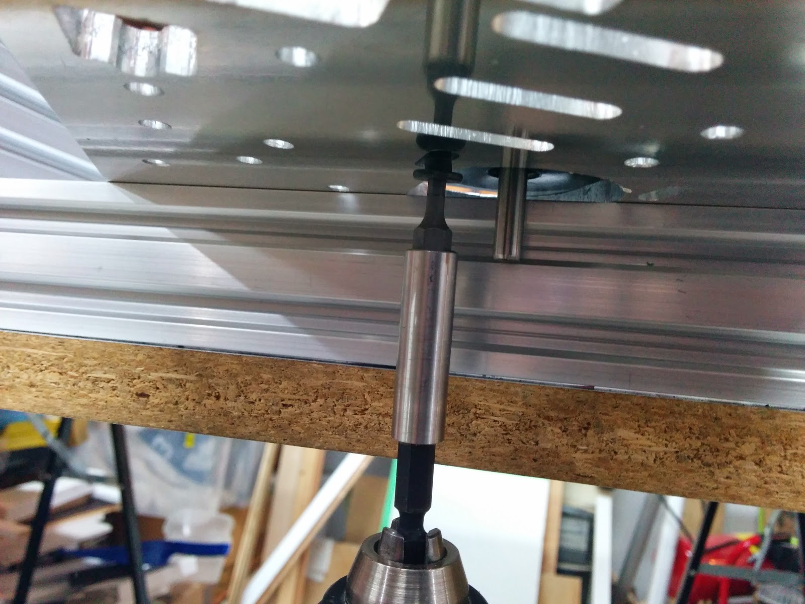
I set the position of the drill chuck such that I’ve tapped the right length when the drill chuck is flush with the jig:
After tapping the first hole, test it with one of the M5 bolts you’ll be using (that’s how I discovered I had the wrong tap):

Tapping the hole may raise a slight ridge around the edge of the hole:
I have a hand-held countersink that I use for deburring holes:
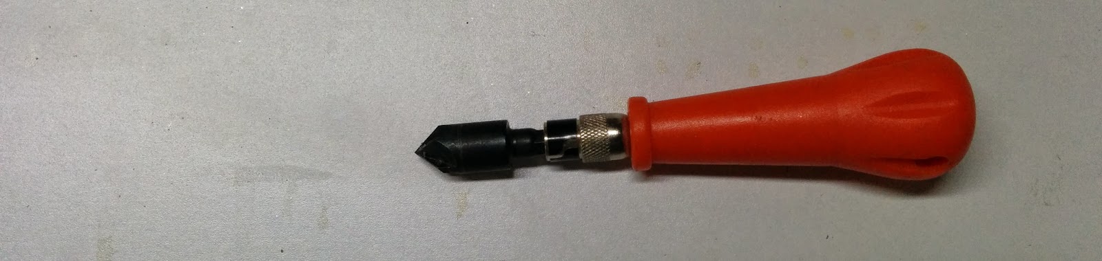
You could use a larger drill bit in a pinch. Here’s the tapped hole after being deburred:
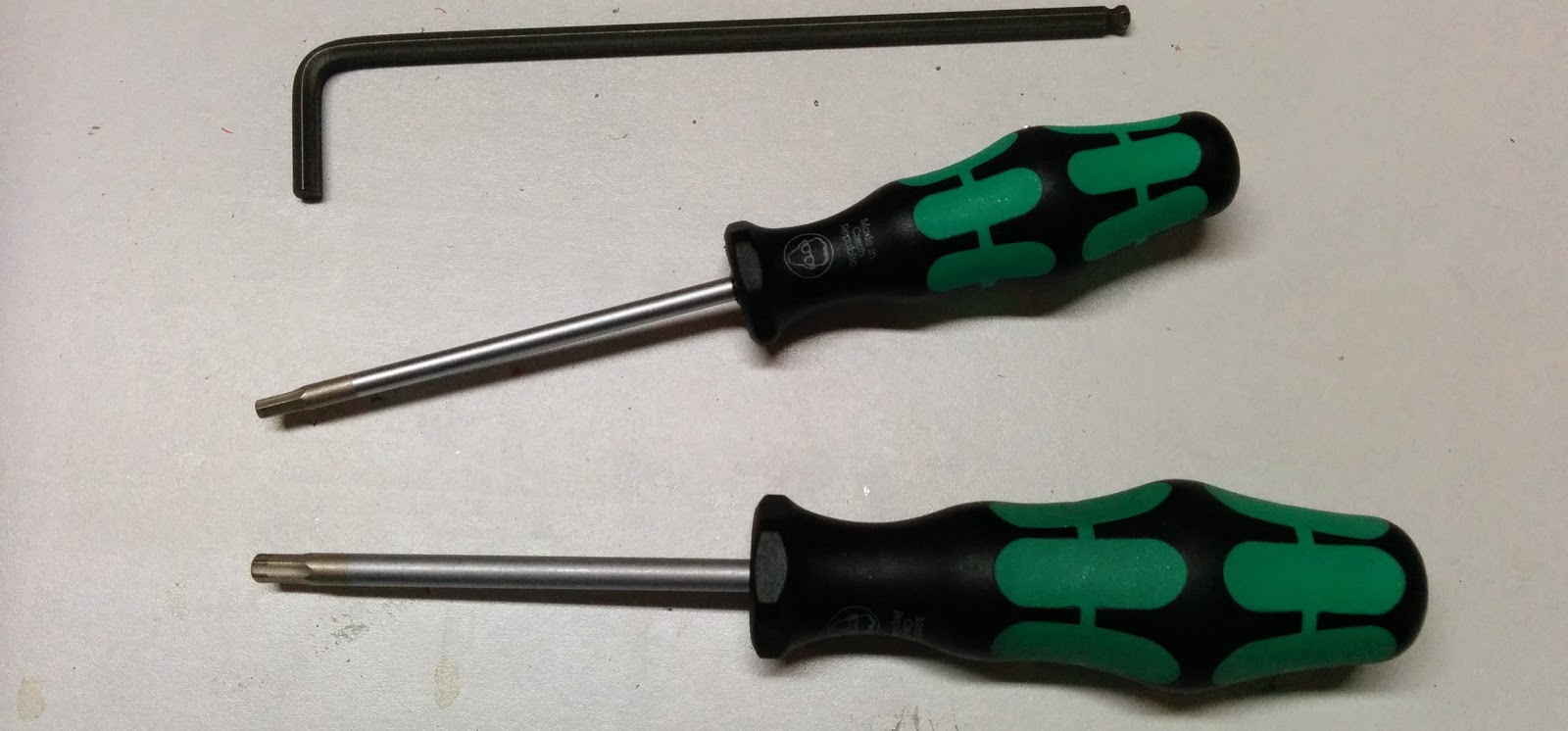
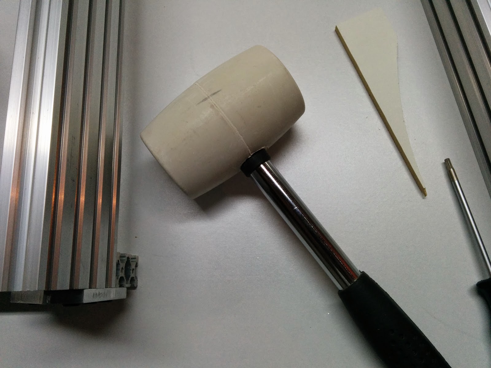
I prefer using screwdriver style allen wrenches most of the time. The low profile M5 socket head cap screws (SHCS) need a 3mm allen wrench. The full head M5 SHCS screws use a 4mm allen wrench. I also used an 8mm nut driver (I forgot to take a photo).
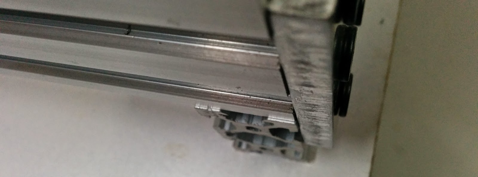
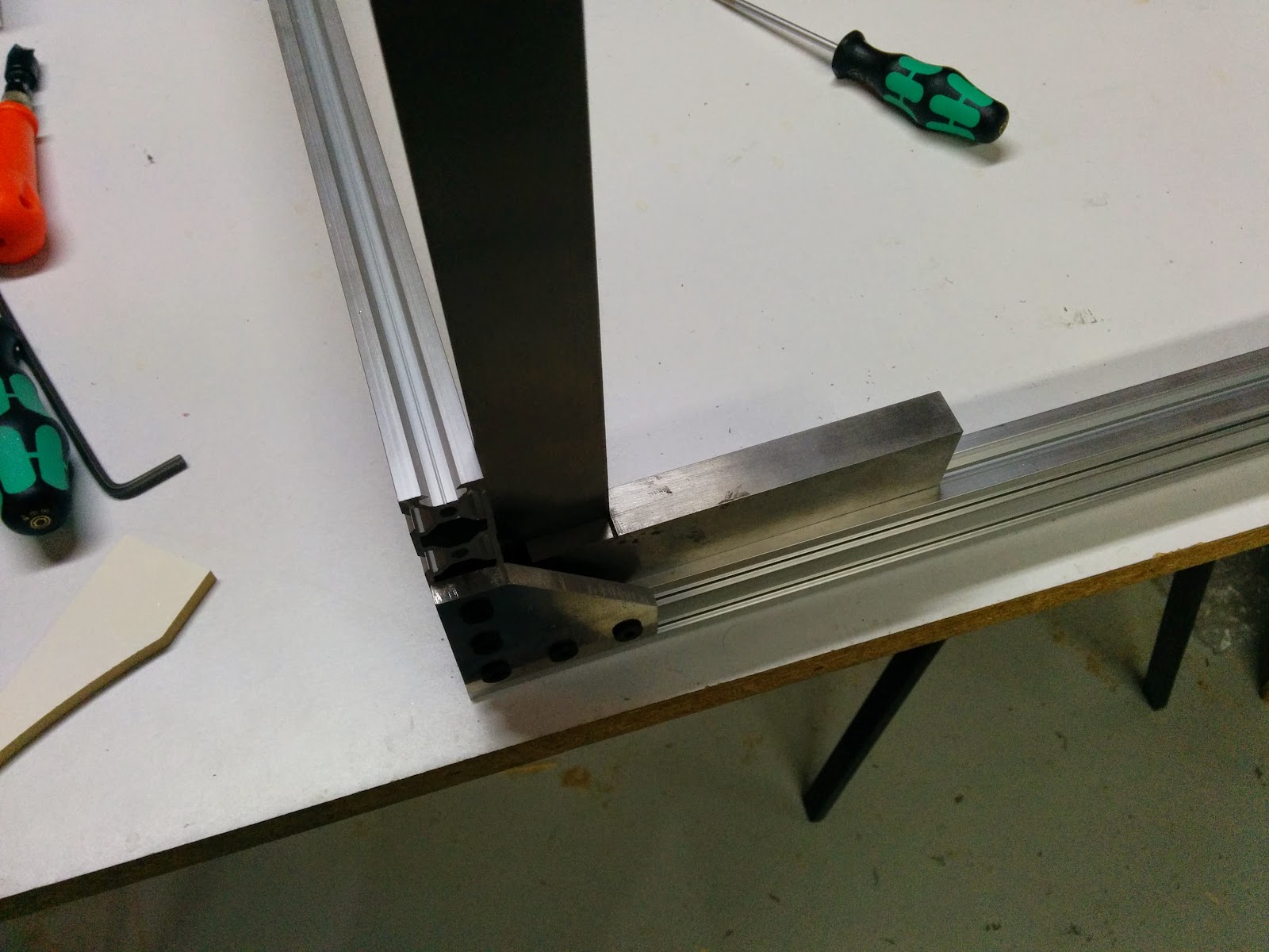
When assembling the frame, check to see that the bottom piece is flush with the side. In this photo you can see the top of the lower extrusion:
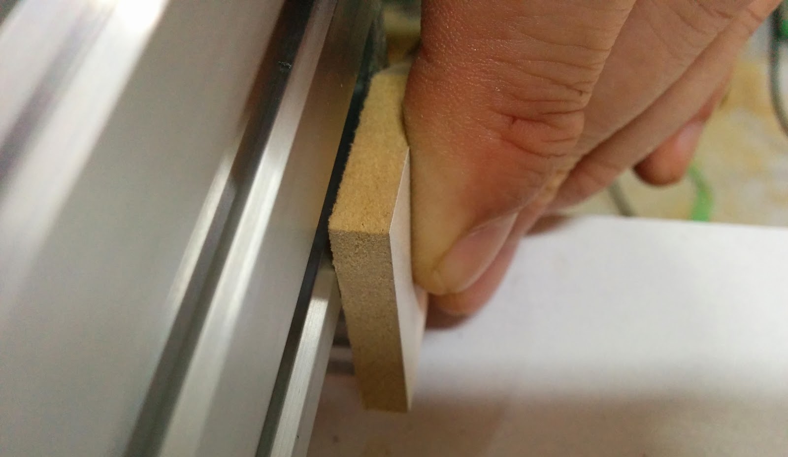
I use a scrap of wood or metal
And when that doesn’t work, I use a few gentle taps with a “persuader”. The rubber head won’t mar the extrusions.
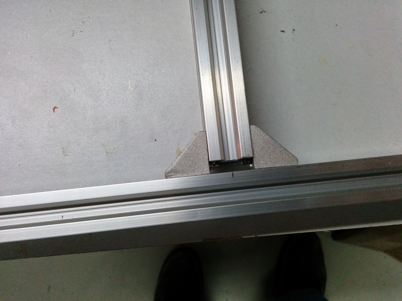
When installing the center supports, it’s normal to have a small gap (in my case it was about 5mm), so I split the difference and made the gap about the same on both ends:
Check for squareness:
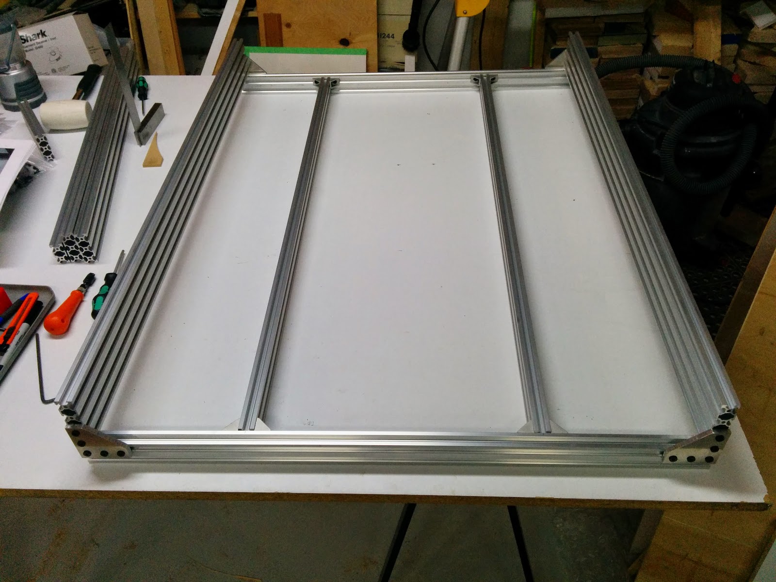
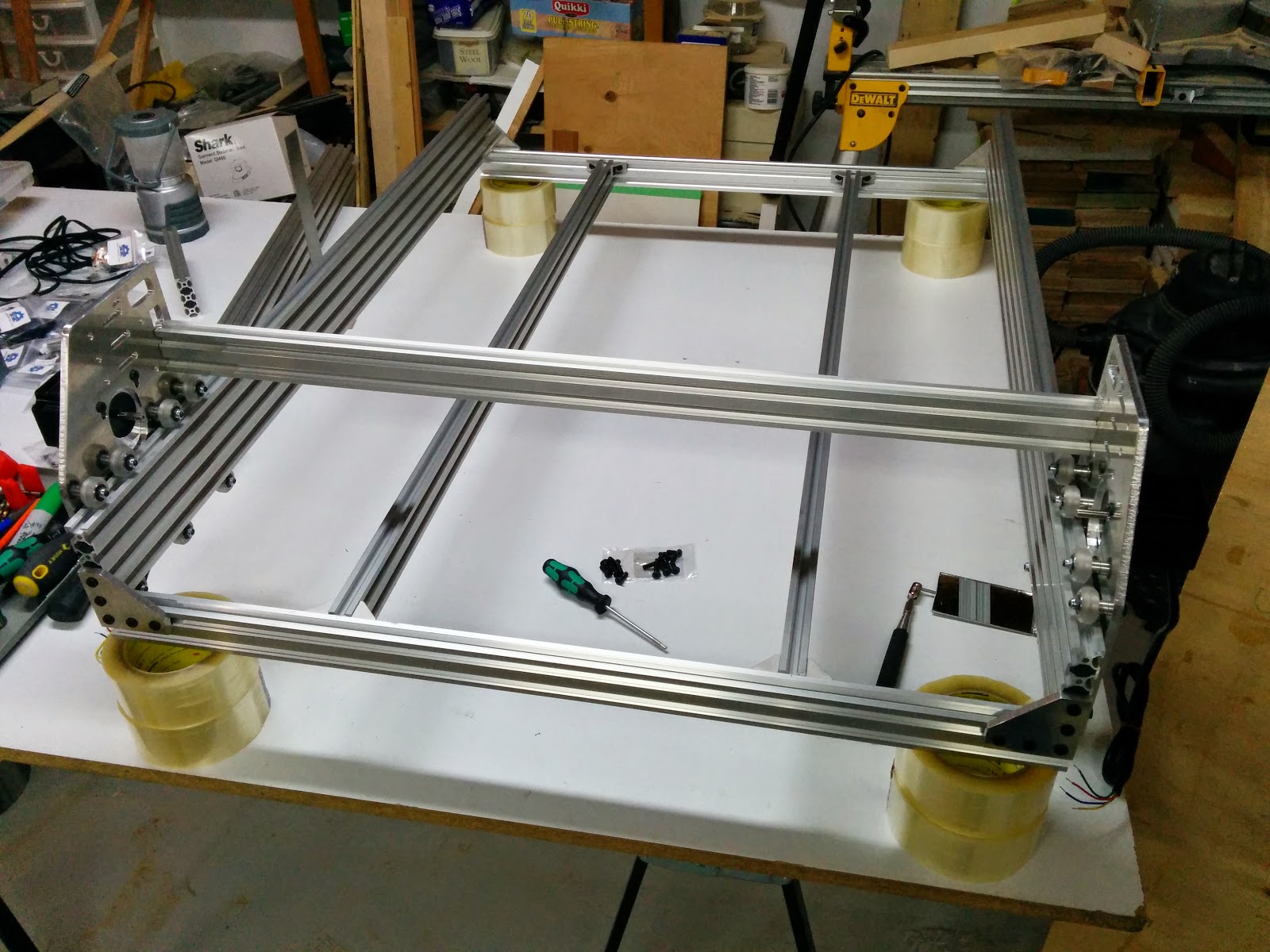
Here’s the frame all put together:
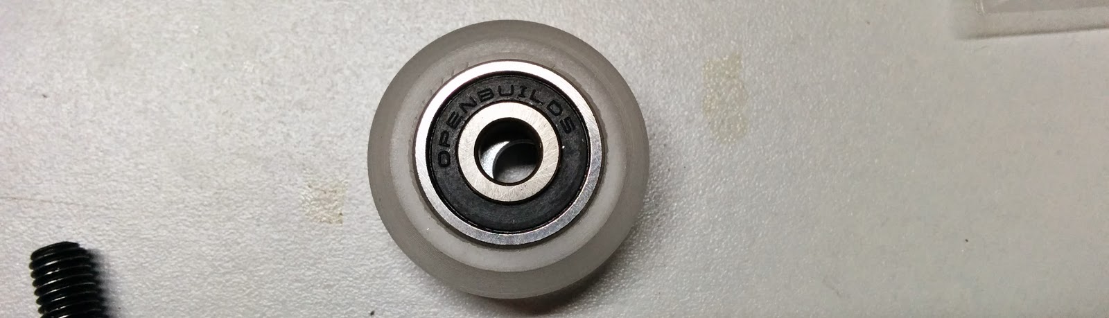
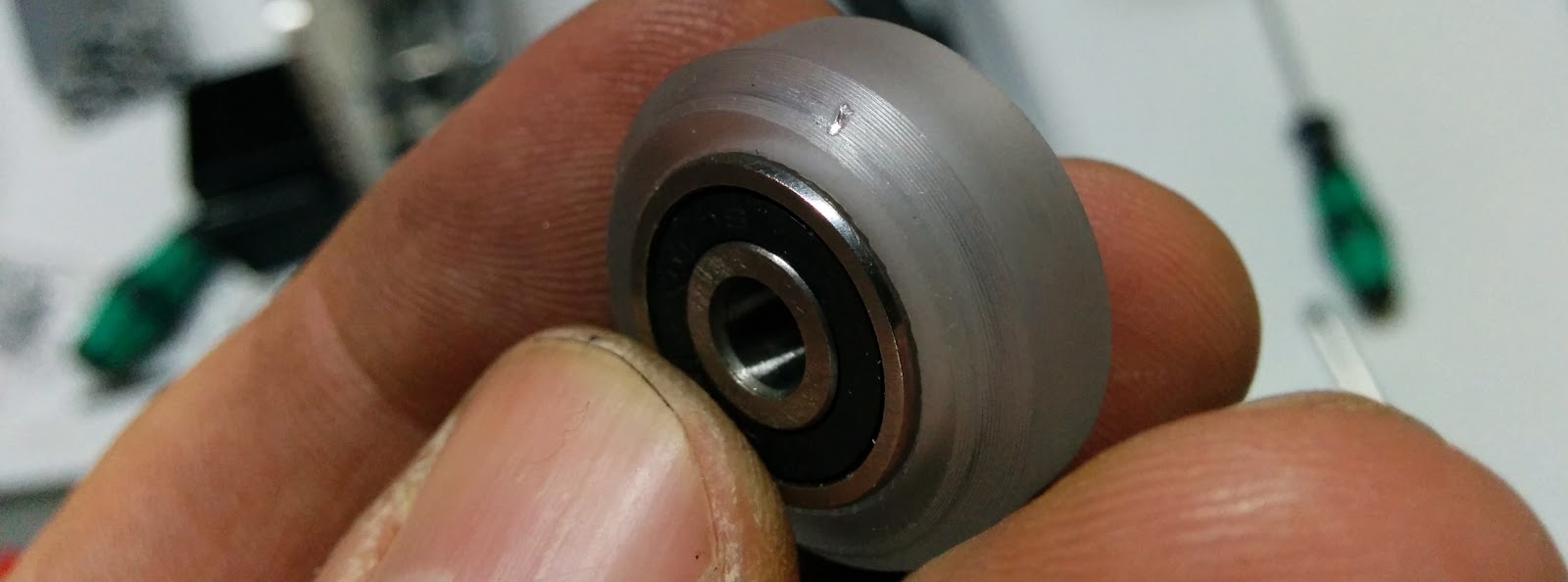
On to the gantry. When putting the OpenBuild wheels together, make sure you put the supplied washer between the 2 bearings:
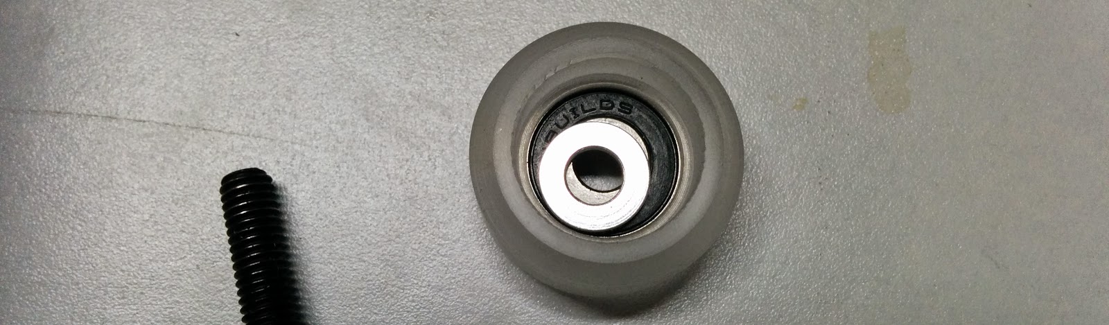
I use a small allen wrench to move the washer around afterwards so that the hole lines up:
The side of the eccentric closest to the hole has a wide slot on the face. I fill that in with a black sharpie to make it easier to identify later.

I also use a center punch and a different color marker to mark the opposite side of the eccentric:

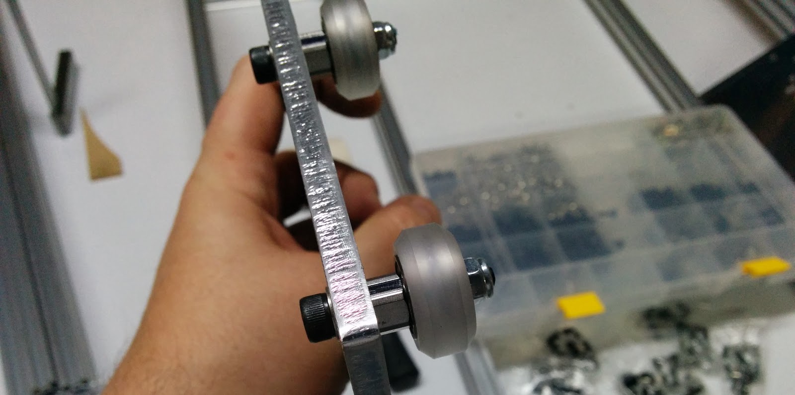
My kit didn’t come woth washers, but I added some under the heads of the M5 bolts since the bolt head doesn’t cover the larger hole for the eccentric. I added them to the non-eccentric ones as well so it looks consistent:

When you initally install the eccentrics, you should put all of the black marks towards the bottom. This puts the eccentric at its loosest position. I put the heads on the outside because I thought it looked better.
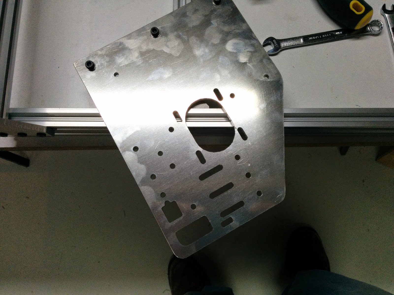
For installing the stepper motor, getting the first bolt in is the most difficult. I lined the edge of the frame with the edge of the table, and put the plate like this:
I then used a 3mm hex bit in my cordless drill
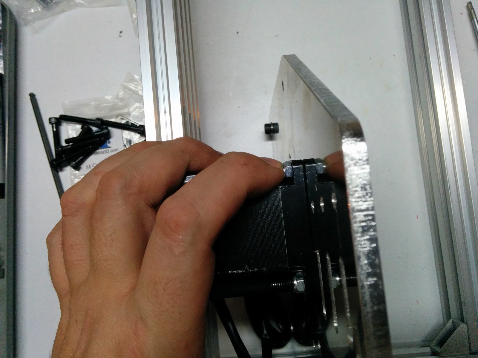
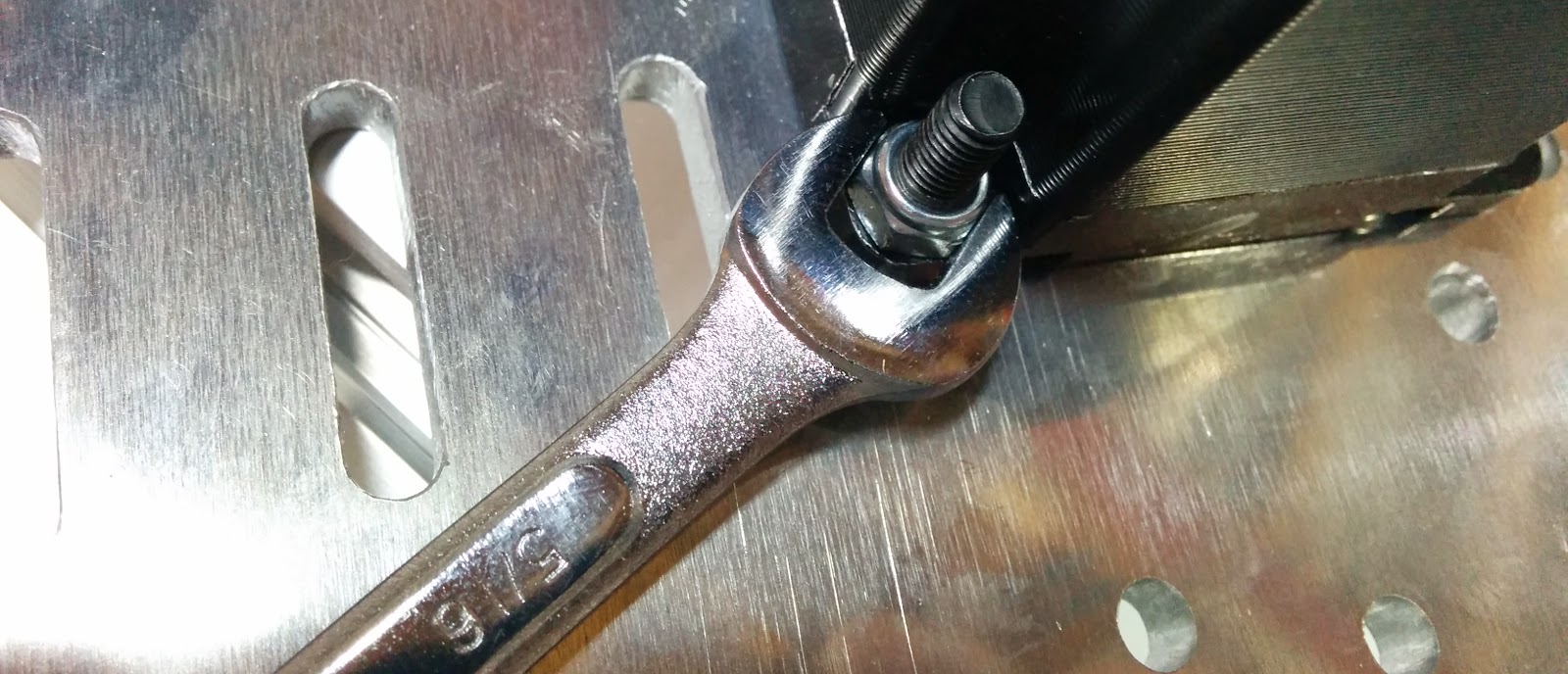
I hold the nut in place against the stepper and start threading the bolt as far as I can by hand. The M5 nuts are 8mm, but 5/16” will also fit. The 5/16” actually tends to fit a little tighter. I use the cordless drill to get the nut almost all of the way on:
I found I had to jam the wrench between the nut and the stepper. I tightend up the last little bit by hand so I didn’t over tighten using the cordless drill.
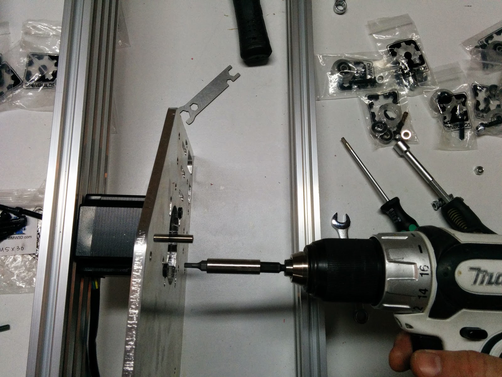
Once the first bolt is on, the remaining three are much easier and could be done from a more convenient position:
On my left plate, even with the eccentrics in the loosest position, the wheels were a bit tight. So I took the bottom wheels off, very slightly filed the holes a wee bit larger (maybe 1/2 mm) and reassembled.
I could also feel a slight period bump as I was moving the left side forward and backward. I eventually discovered this: Oops I wasn’t as careful as I should have been with the swarf from tapping:
I put the steppers at the highest position, and you can’t really use the screws to adjust tension on the belts. I’ll probably figure out a way to adjust the belt tension from the ends of the belts.

I tightened the eccentrics so that I could just barely make the wheel slip using my thumb and one finger, while preventing the plate from moving with my other hand.
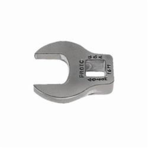
I used a 10mm wrench to adjust the eccentrics, and I had to raise the entire frame up in order to adjust the eccentrics.
I think I’ll pick up (or maybe machine) a crowfoot wrench to allow these to be adjusted without raising the frame:
It took me about three hours to get to this stage of the construction (includes time for taking all of the photos).
Related: Unboxing, Part 1, Part 2, Part 3, Part 4, Part 5, Part 6, Clamps