OX Build - Part 6 - Spindle and First Cut
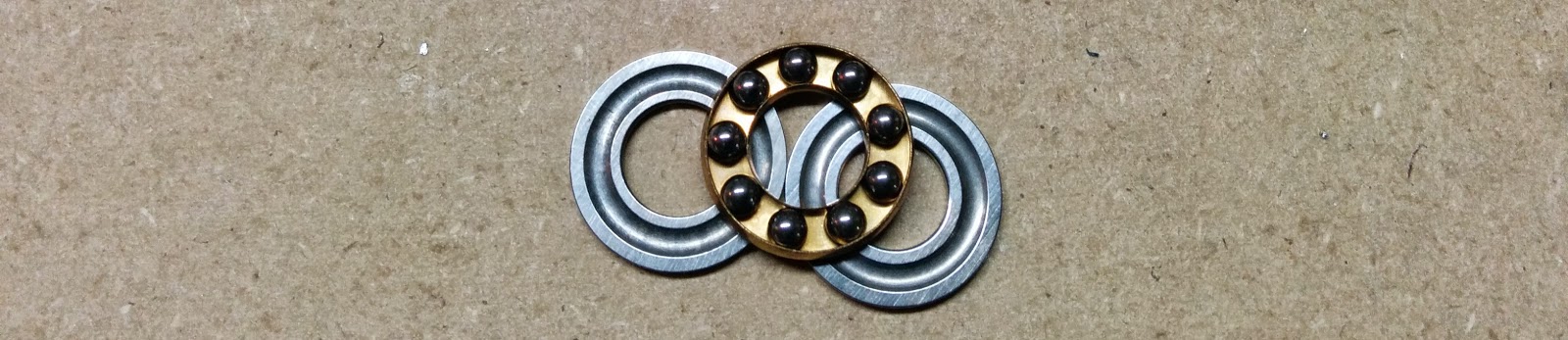
Since I decided to change my Z-axis bearings to proper thrust bearings, I was
concerned about getting dust in the bearings.
Related: Unboxing, Part 1, Part 2, Part 3, Part 4, Part 5, Part 6, Clamps
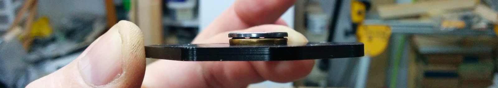
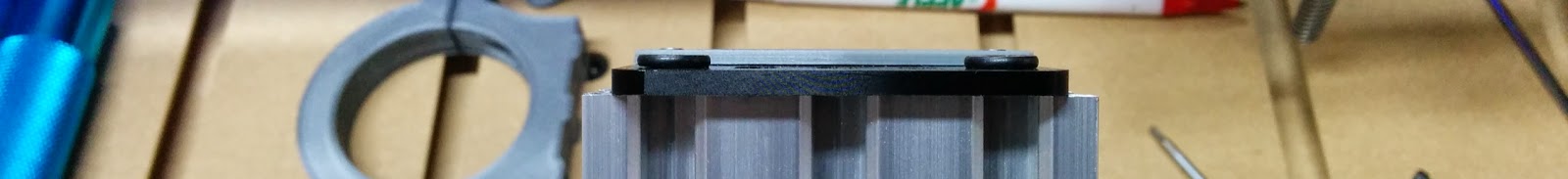
Here’s a side view of the thrust bearing:
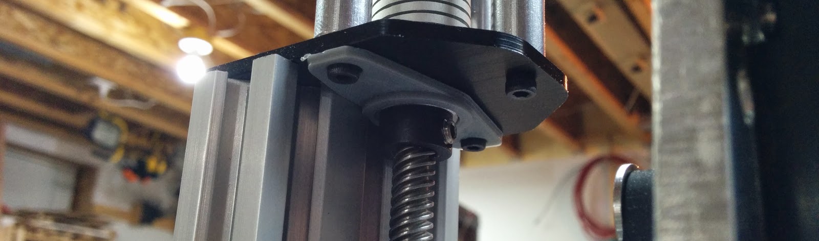
I also noticed that the leadscrew was projecting below the bottom of the z-axis:
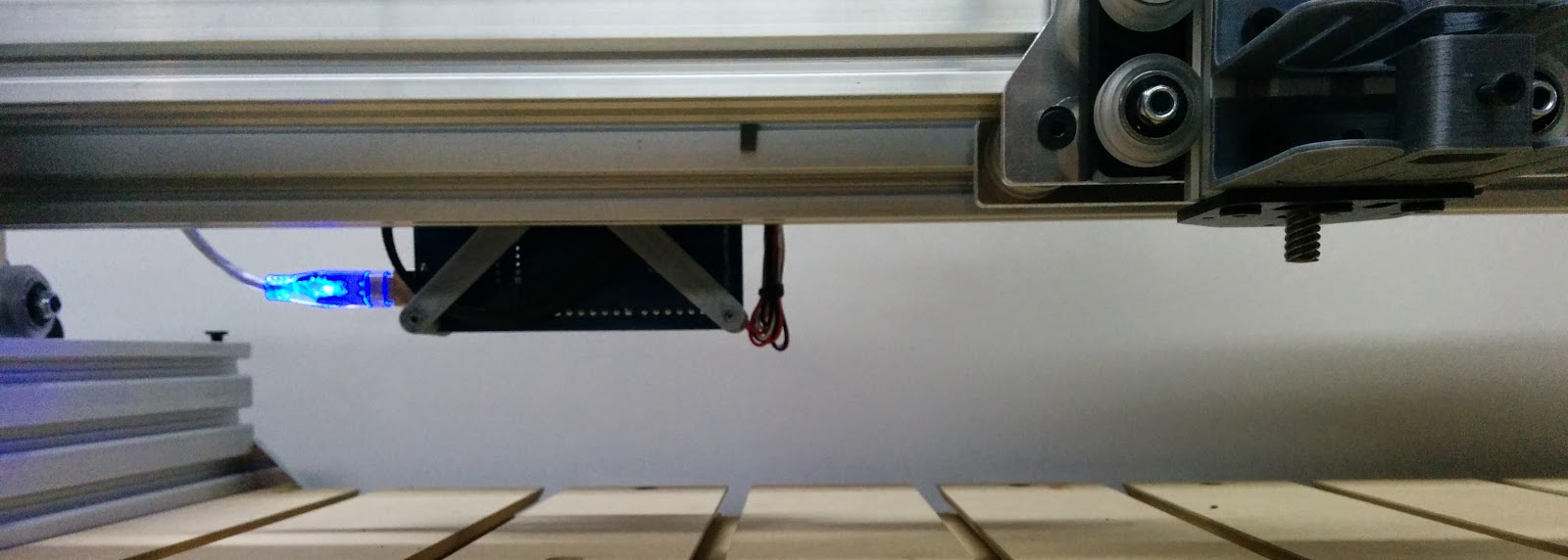
I also noticed my TinyG hanging below the cross bar, so I’ll need to fix that as well. I wouldn’t want that to catch a clamp. I cut the bottom piece off the end of the leadscrew and printed an end cap and some shields for the thrust bearings:
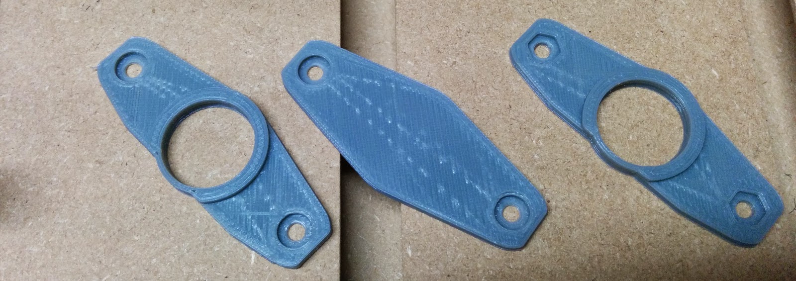
The endcap worked out great, but I had to make a few more refinements to the other 2 pieces in order to have the dust shields not hit the X gantry plate. I forgot to take picttures of the new parts, but you can see the changes in the STL files.
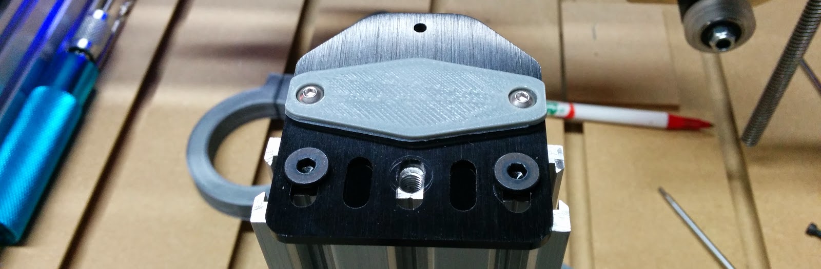
I recessed the screw heads and used button head cap screws, making the dust cap about the same thickness as the low profile screws used to hold the adapter plate:
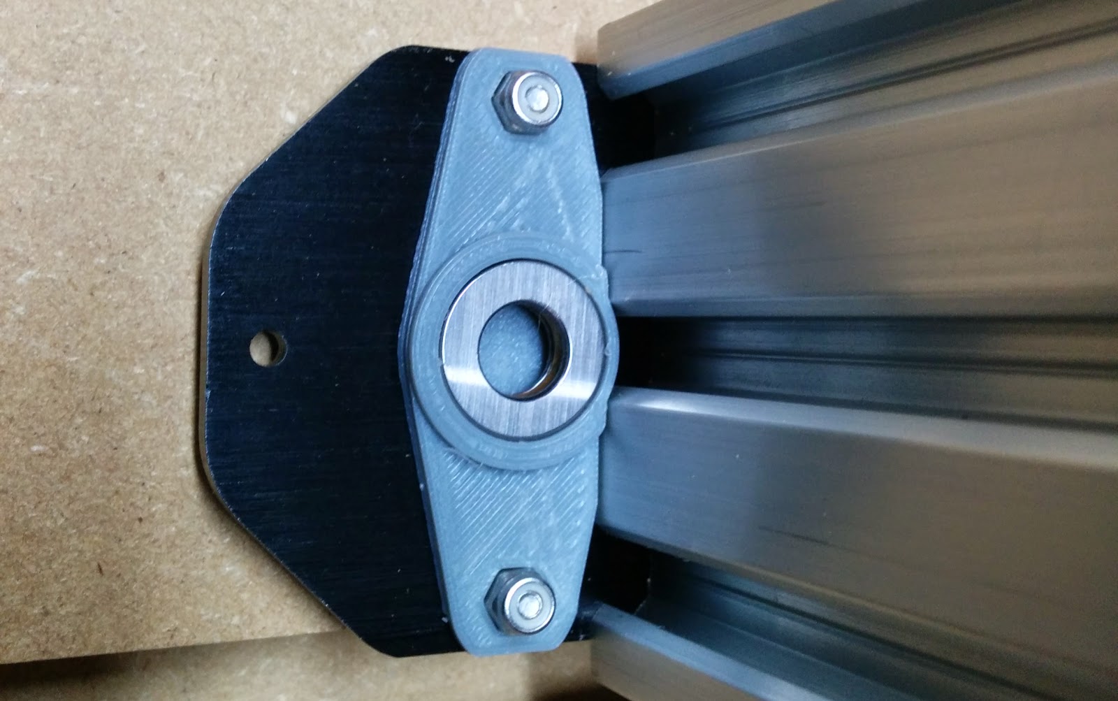
This shows the thrust bearing inside the dust shield on the lower portion:
And the upper portion:
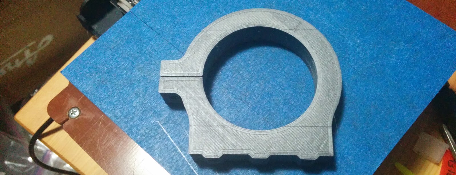
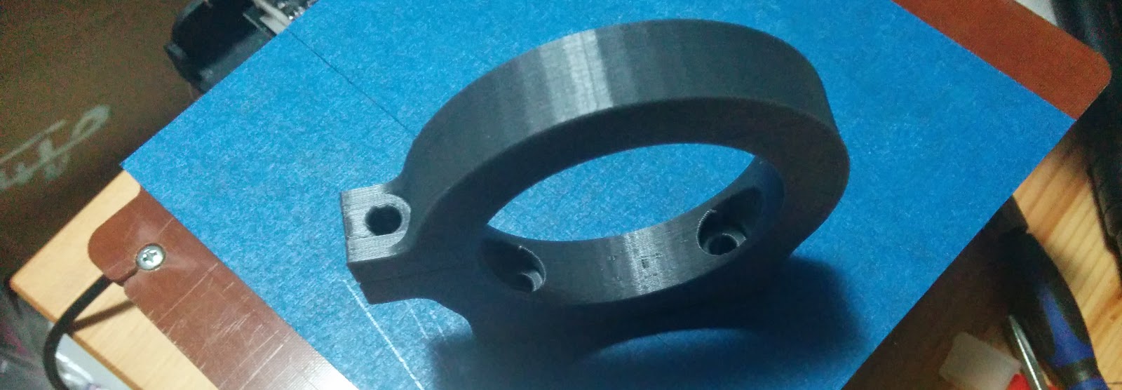
I printed up a spindle mount:
After installing, I don’t like the fact that the mounting screws are hidden once the spindle is installed (but I’ll fix that at a later time):
Here it is with the spindle installed:

And a video showing the Z rapids after a bit of tuning.
Ready to start cutting. Well almost. When I turned the spindle on, I totally lost all of my comms with the TinyG board. I verified that the noise was being introduced in the first cable chain. If I plugged the USB into the TinyG directly then it worked fine. I had two unshielded twisted power lines, so my first attempt to fix things was to replace the spindle power with a shielded cable run. That improved things, but not completely. The USB connection would bounce when the spindle was turned on, but would be usable after that.
I then looked closely at the USB cable I was using:
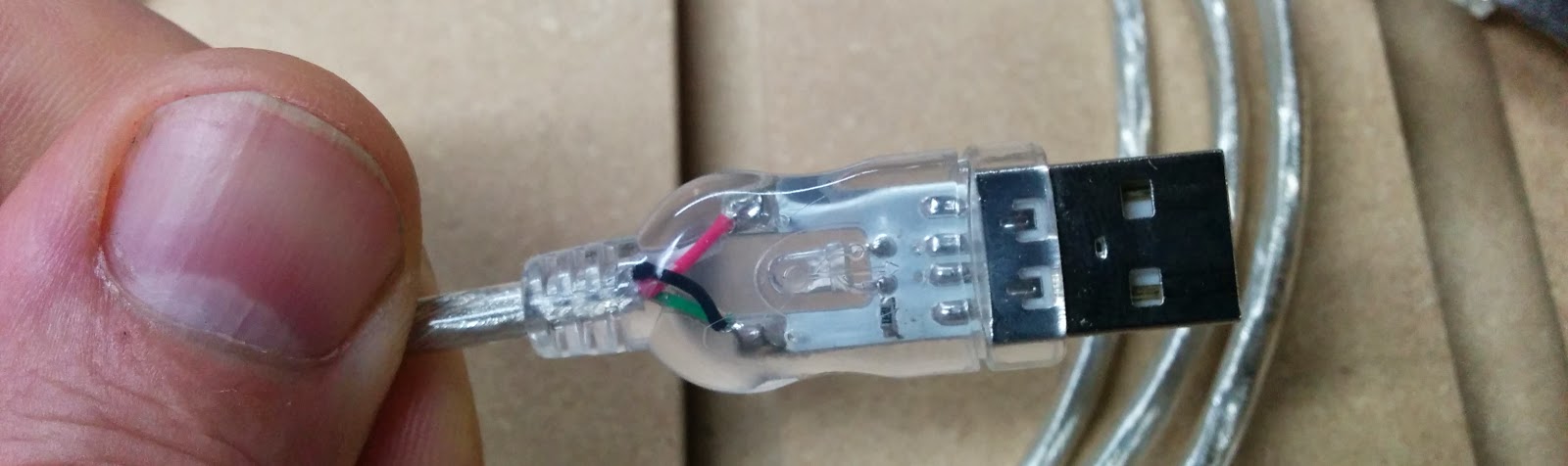
The cable has shielding, but it doesn’t seem to be connected to anything. Sure enough, no connectivity from the shield on one end to the other.
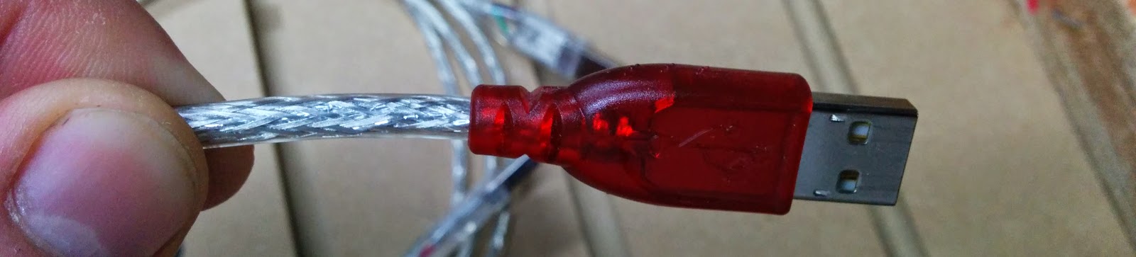
I swapped in another USB cable. My multimeter confirmed that the shield was connected through, and everything works.
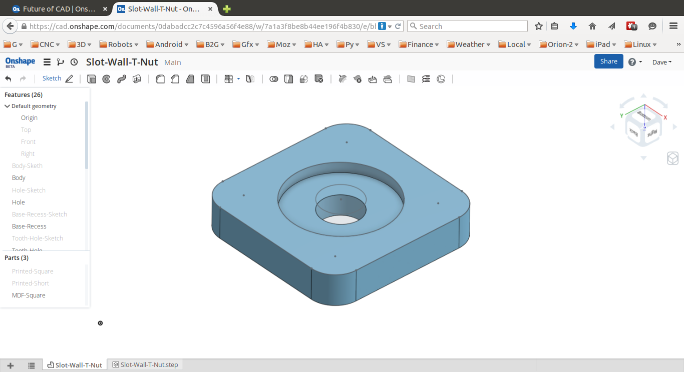
For my first part, I decided to try and create a T-nut out of some 1/4” hardboard. I first designed the part in OnShape:
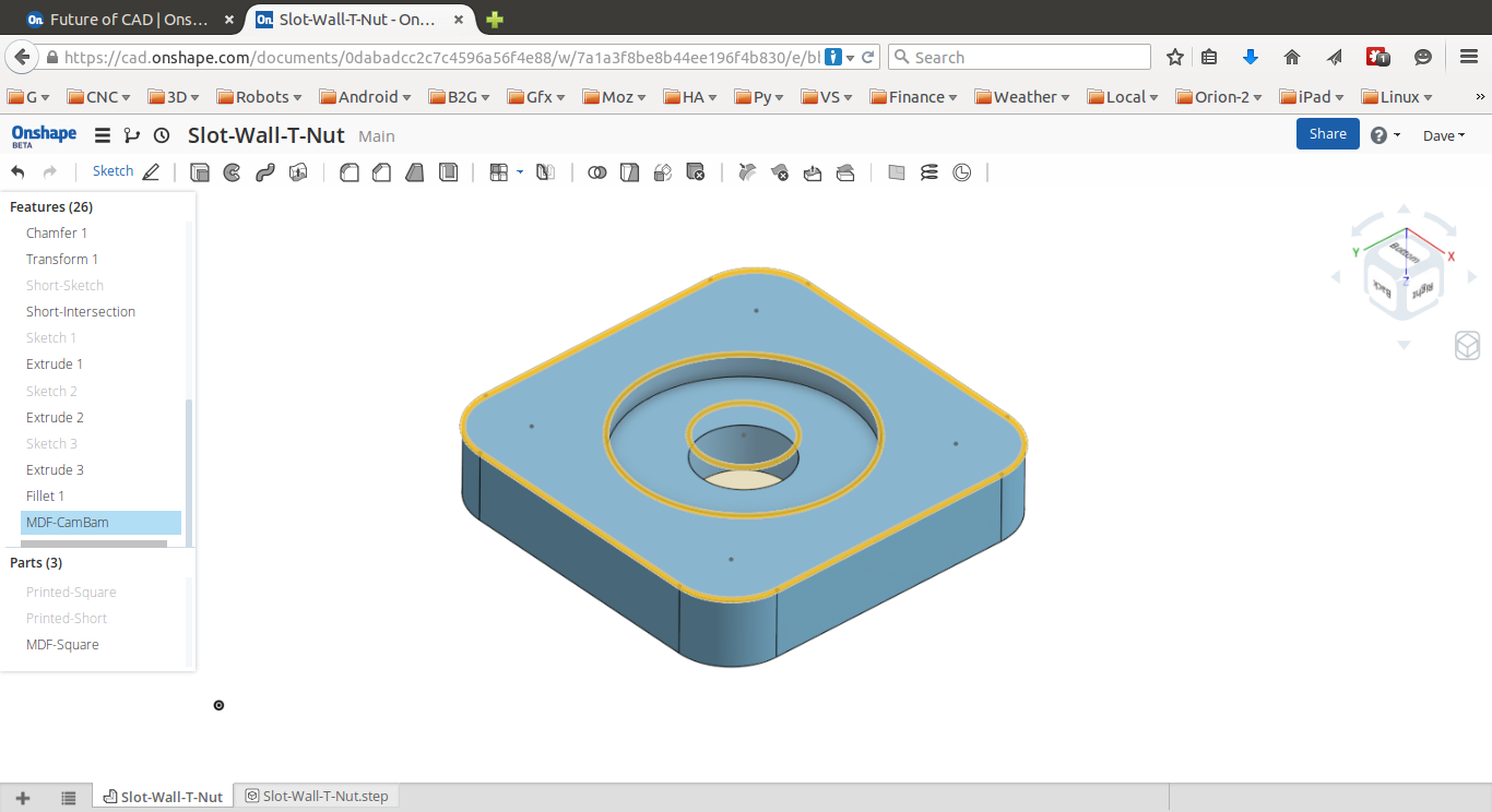
I then created a sketch and “Used” (aka projected) all of the features onto it and exported that sketch as a DXF. The orange lines are the projected features:
I then imported the DXF into CamBam. The white lines are the DXF features. I added a pocket operation for the large recess, a pocket for the center hole that goes through all of the way, and finally, added a profile operation for the outline. CamBam supports tabs, so I added a tab on each side. These are small unmachined pieces which are left behind to keep the main part from moving while performing the very final operations. The tabs are represented by the rectangles you can see. If you look at the toolpath (blue and green lines except for the tabs) you can see that Z rises up to leave the tab behind:
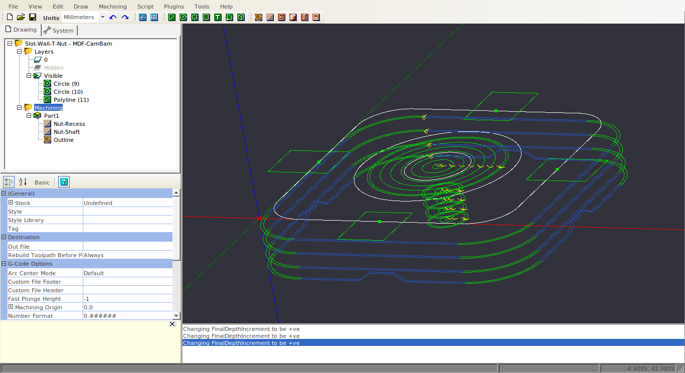
I used a 3.175mm endmill for all of the operations, 600 mm/min feedrate, 100 mm/min plunge rate. The recommended depth of cut for MDF is 50% of the tool diameter, so I used numbers around 1.5mm for the depth increment, and for the final profile I used a cut width of 4mm so that the first cut (which is full width of the cutter) wasn’t the final cut. The final cut would wind up being 4
- 3.175mm = 0.825mm, which will generally give a better finish than the finish on a full width cut.
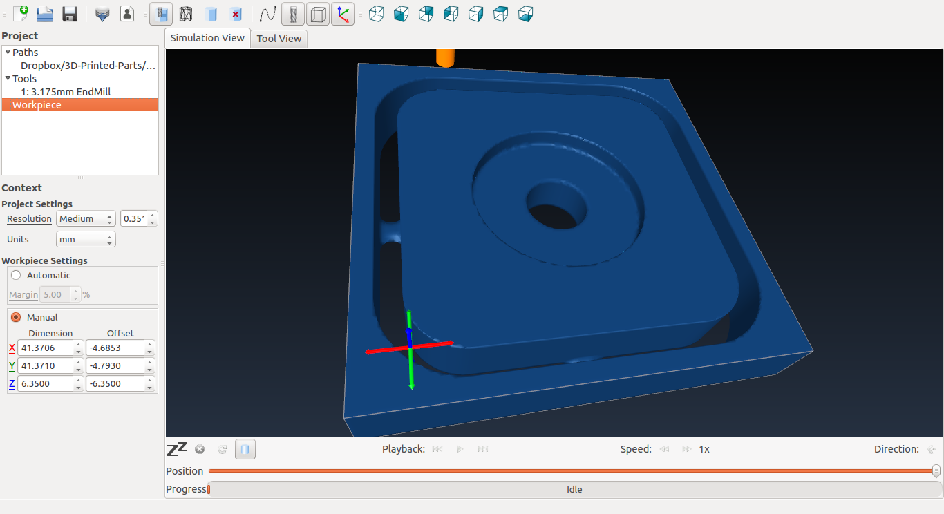
I then generated the gcode, and ran it through OpenSCAM to verify that everything looked good:
Here’s a video of the first cut:
And a photo of the finished cut:
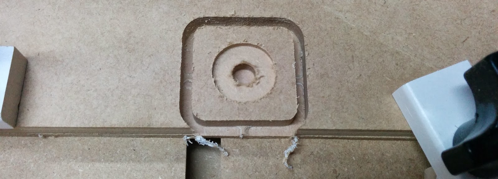
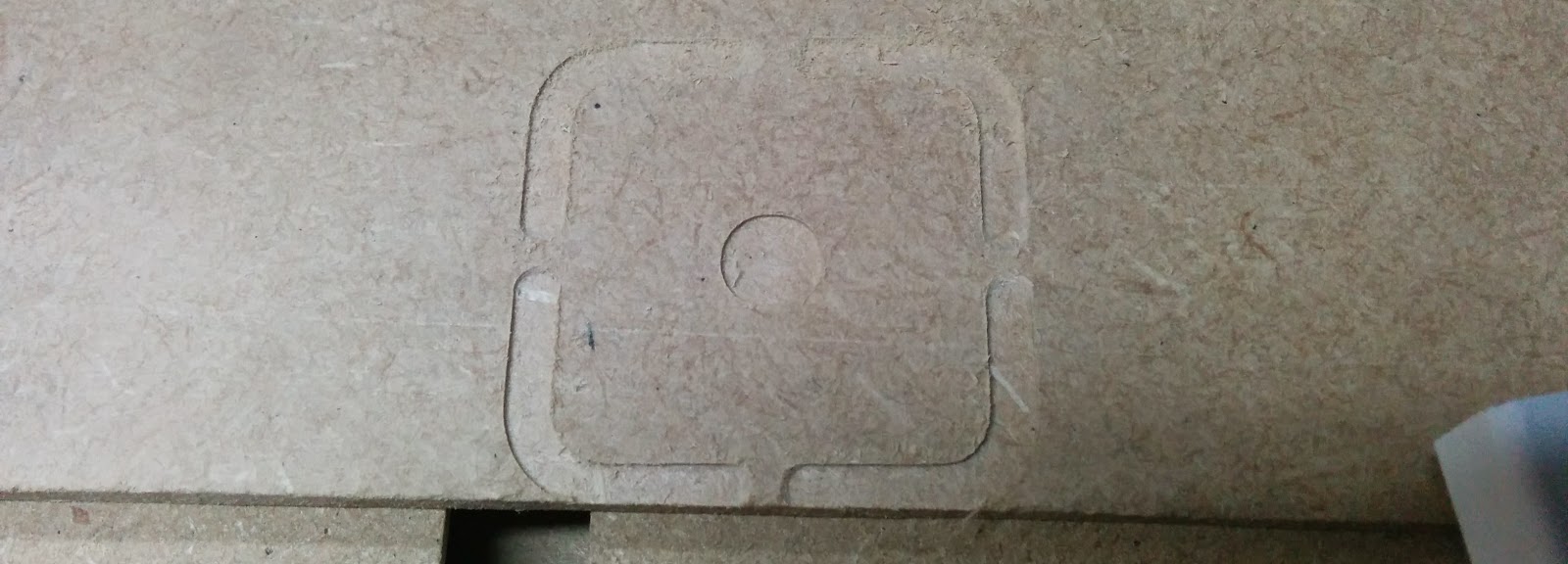
And the spoiler board (I used some 1/8” hardboard). My total cut depth was 6.85mm for the 6.35mm (1/4”) material:
This shows the tabs:
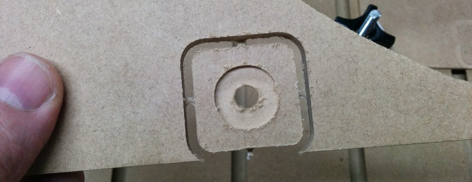
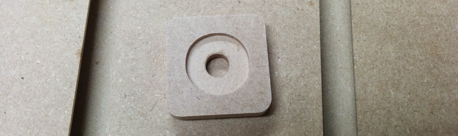
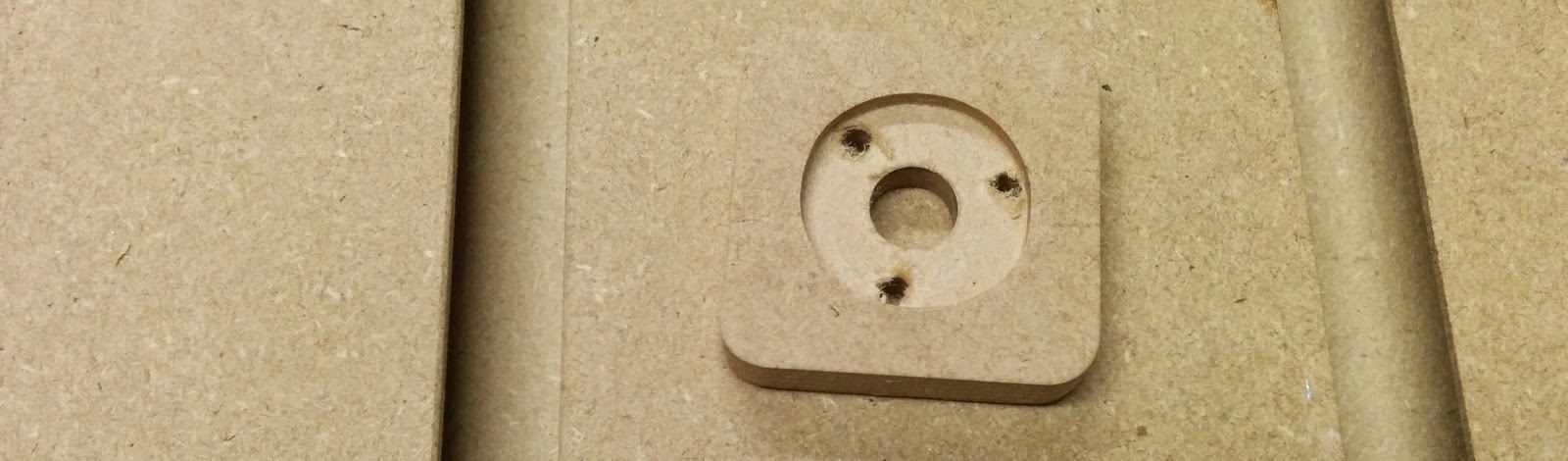
This is the T-nut cleaned up a bit:
The metal propel nut didn’t want to go in, so I woud up drilling 3 extra holes:
And now the propel nut goes in fine:
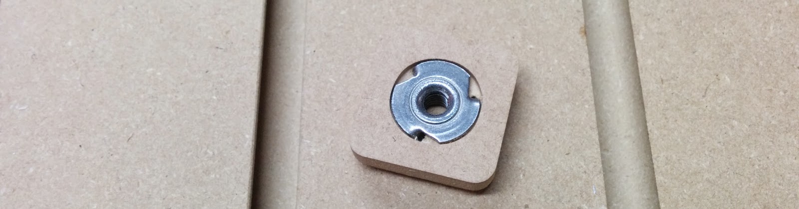
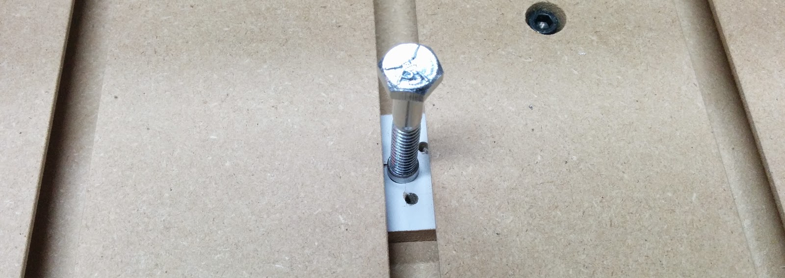
So I’ll have to modify my model to drill those 3 extra holes. Here’s the T-nut in the slot:
I since discovered that you can import STLs into CamBam:

which doesn’t look all that impressive. However, if you select the Surface, and then choose Edit->Surface->Edge Detect, and then delete the Surface object, you’ll wind up with this much nicer looking wire frame:
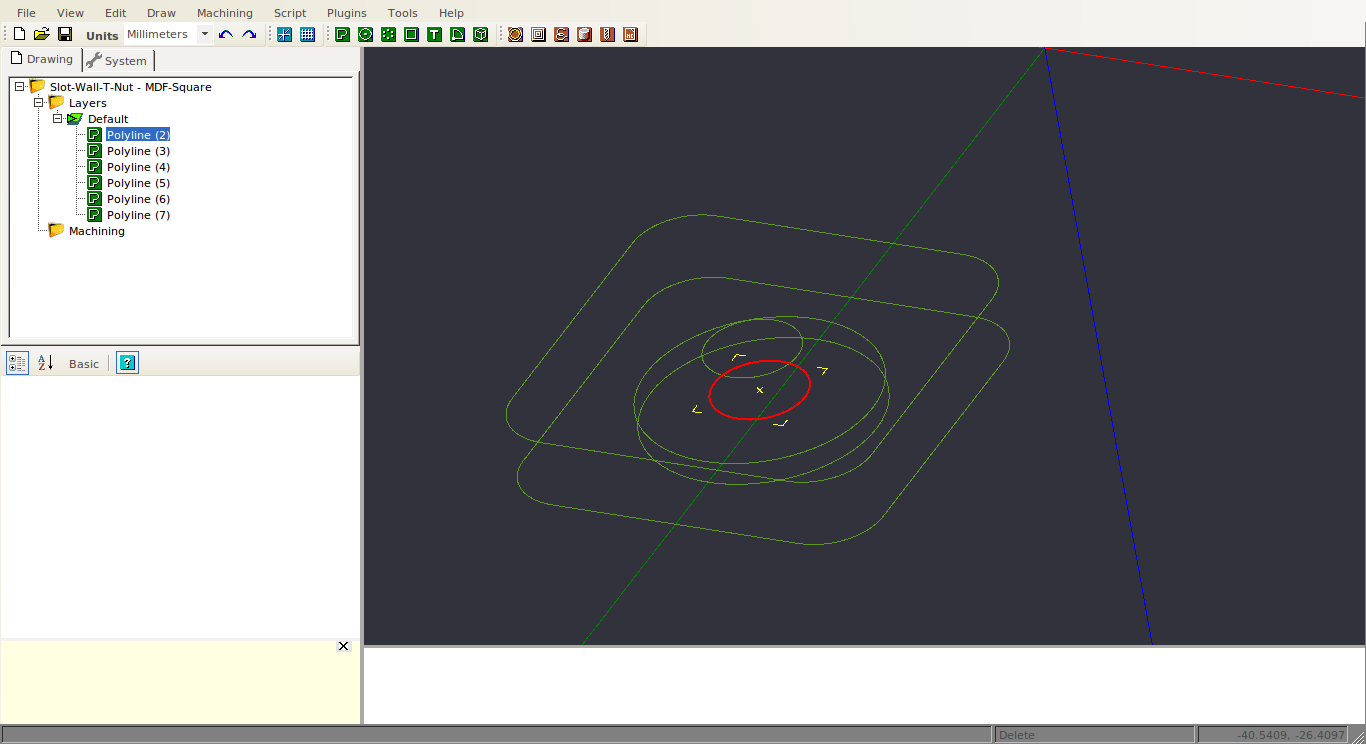
And you can click on polylines from the wireframe to perform machining operations with.
I used the 3D printed T-nuts, a few scraps of wood with drilled holes, some all thread and knobs for my first clamps:
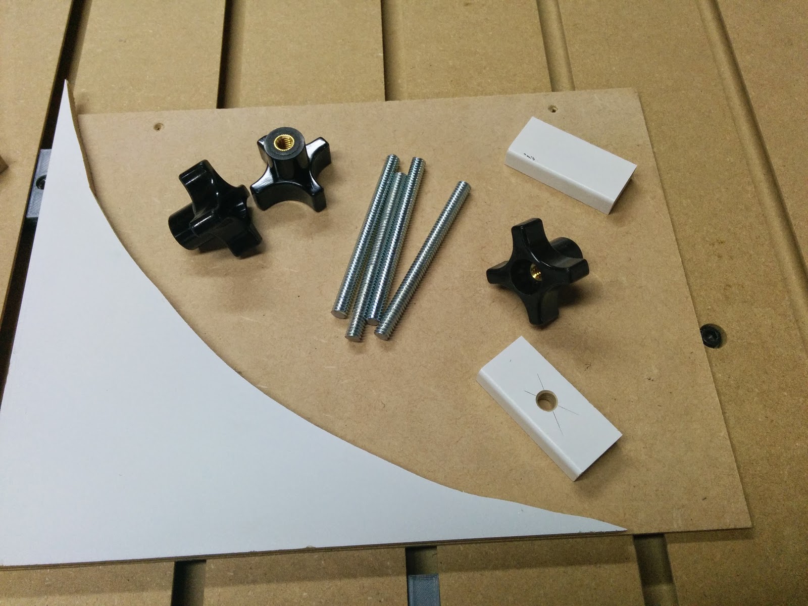
I think my next project will be some decent clamps.
3D Printed Parts:
| Dust Cover | OnShape | STEP & STL |
| 52mm Spindle Mount | OnShape | STEP & STL |
Related: Unboxing, Part 1, Part 2, Part 3, Part 4, Part 5, Part 6, Clamps