OX Build - Part 4
Now that the basic mechanical stuff is done, it’s on to the electronics.
Related: Unboxing, Part 1, Part 2, Part 3, Part 4, Part 5, Part 6, Clamps
I had some surplus cable chains that I salvaged off another machine, so the first order of business was to create mounts for them. Right around this time, I also discovered onshape.com which is a free online solid modelling CAD site. You need to request a beta invite. This took a day for me, but other people I’ve talked to have gotten their accounts activated fairly quickly.
In the event that any of the 3 printed parts are useful to someone, I’ll be making all of the parts public under OnShape, and will provide URLs to the parts, to STEP files, and to the STL files. I’ll put a table with links to all of the 3D printed parts at the end of the post.
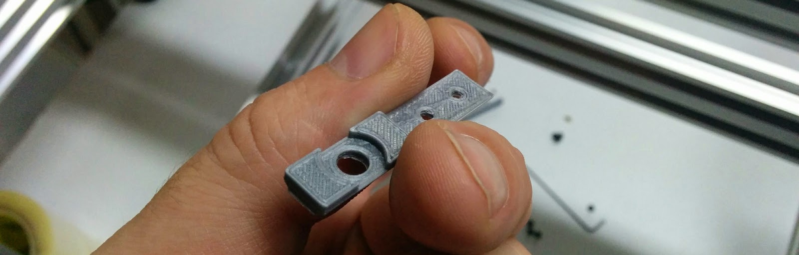
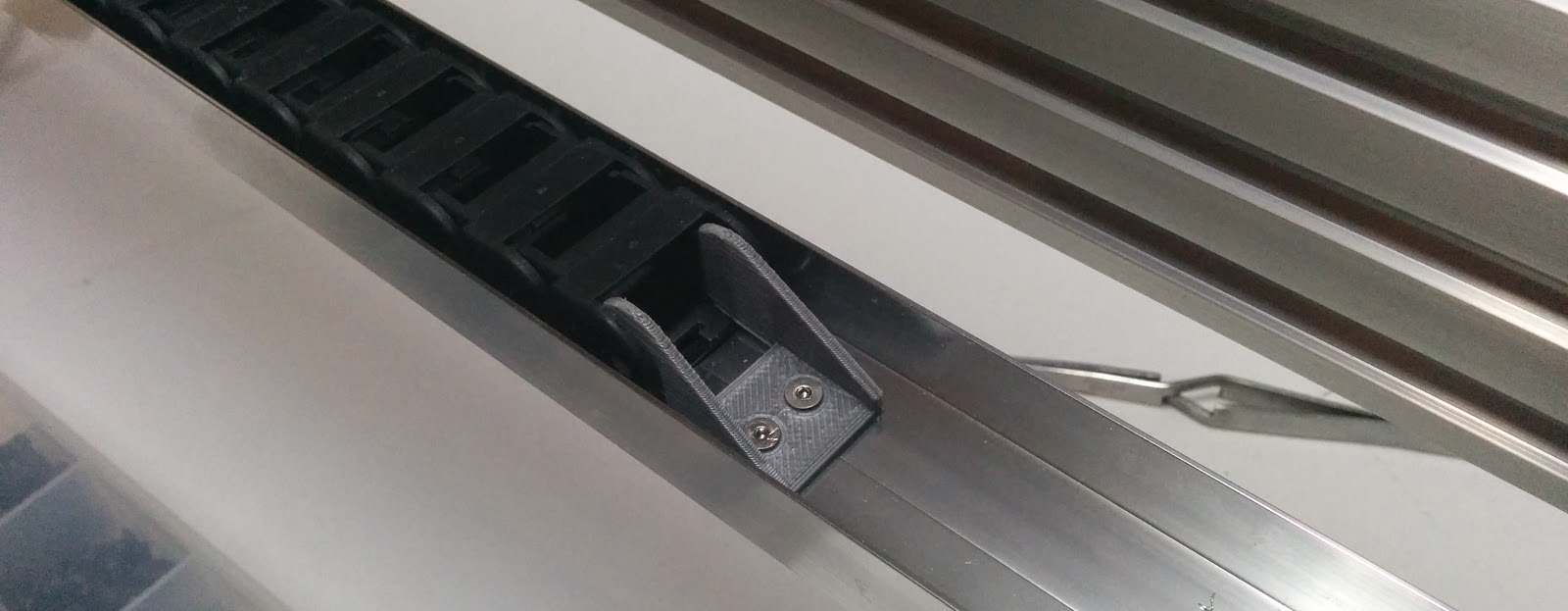
This is the lower X cable chain mount. This fits in the V-Slot.
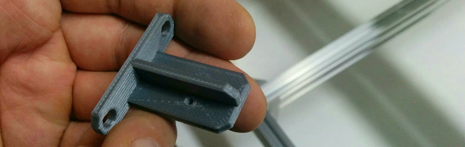
The upper X cable chain mount (goes above the stepper):
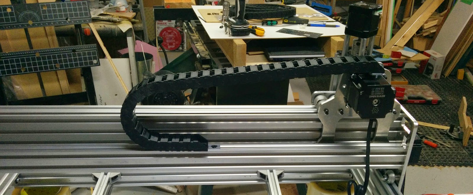
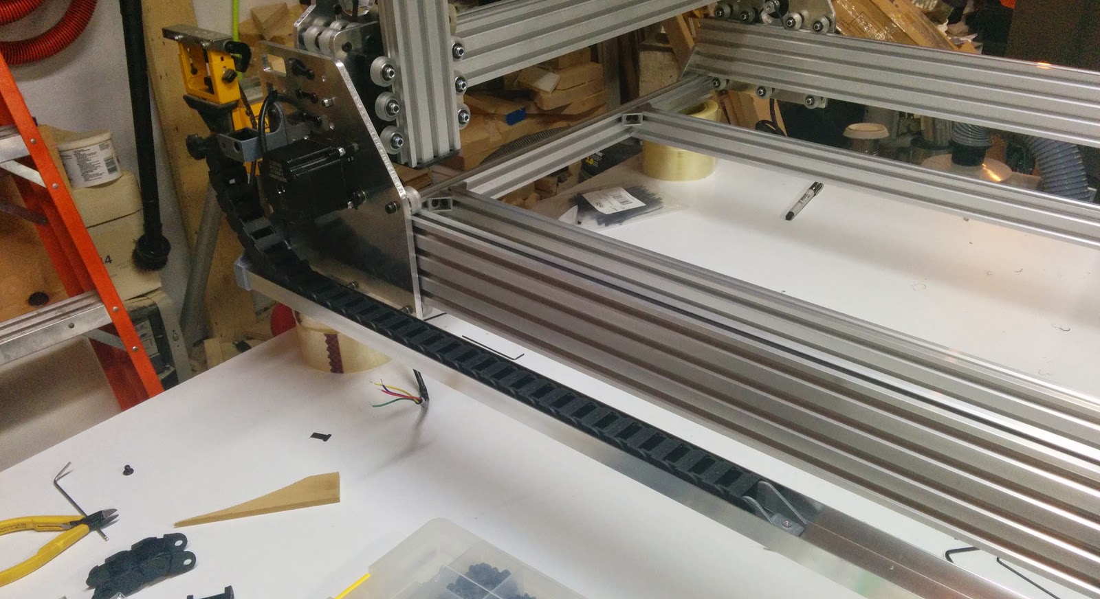
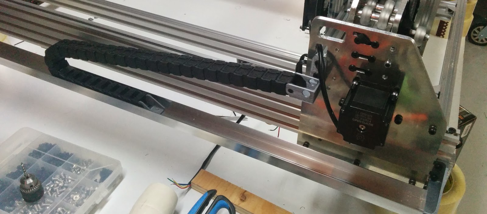
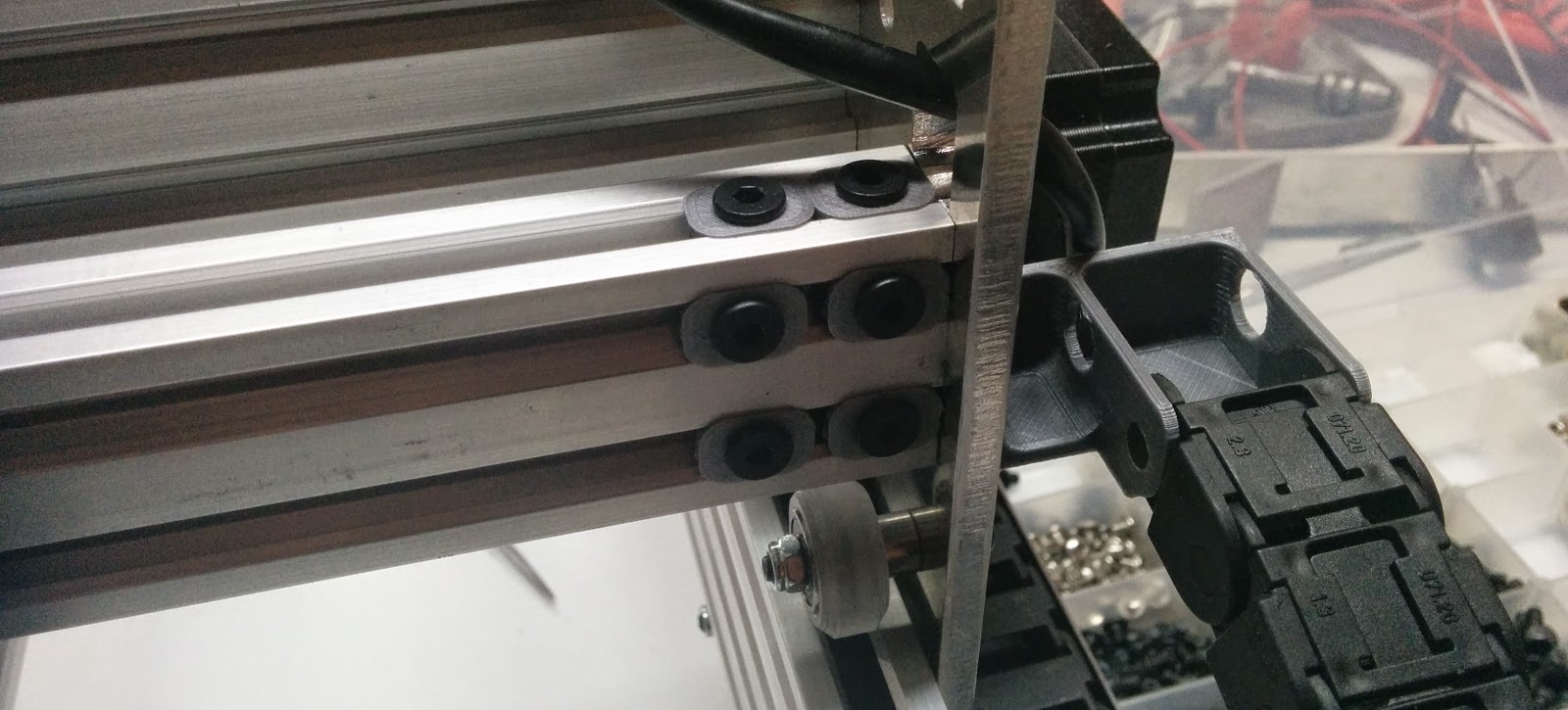
Here’s the X cable chain mounted:
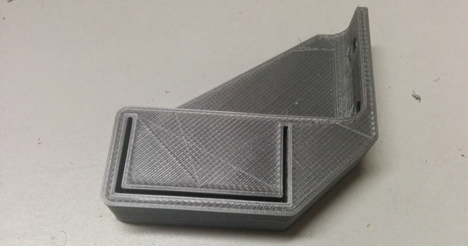
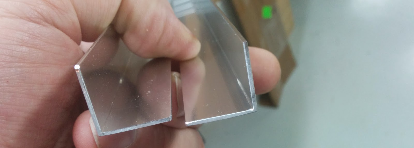
For the Y cable chain, I wanted something to support the cable chain. I used two pieces of 90 degree trim pieces I found at Home Depot. This is the mount I designed:
This is what the 90 degree angle pieces look like (they’re about 3/4” on each side):
The 90’s fitted into the mounting piece:
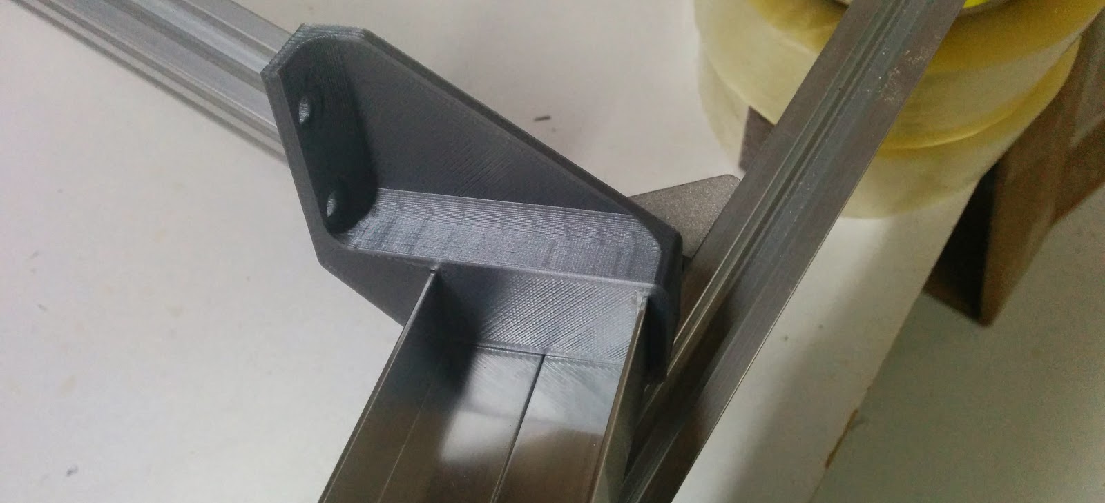
And the Y cable chain support in place:
This is the upper mount for the Y cable chain:

With the cable chain attached:
And the lower mount. Since this is near the middle of the support, it also helps to hold the 90 degree channels together as well.
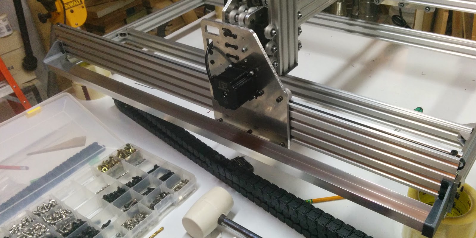
Gantry all of the way back:
Gantry all of the way forward:
The cable chain for the Y axis was Igus Zipper chain, so one of the sides is removable, which makes putting the cable in a bit easier:

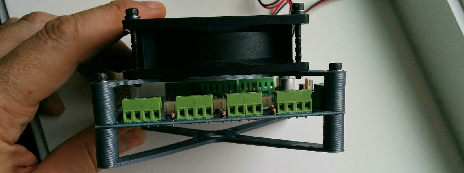
I printed a temporary mount for the TinyG board (I’ll eventually use a metal enclosure). The 4 holes in the middle will mount on the rear of the gantry.
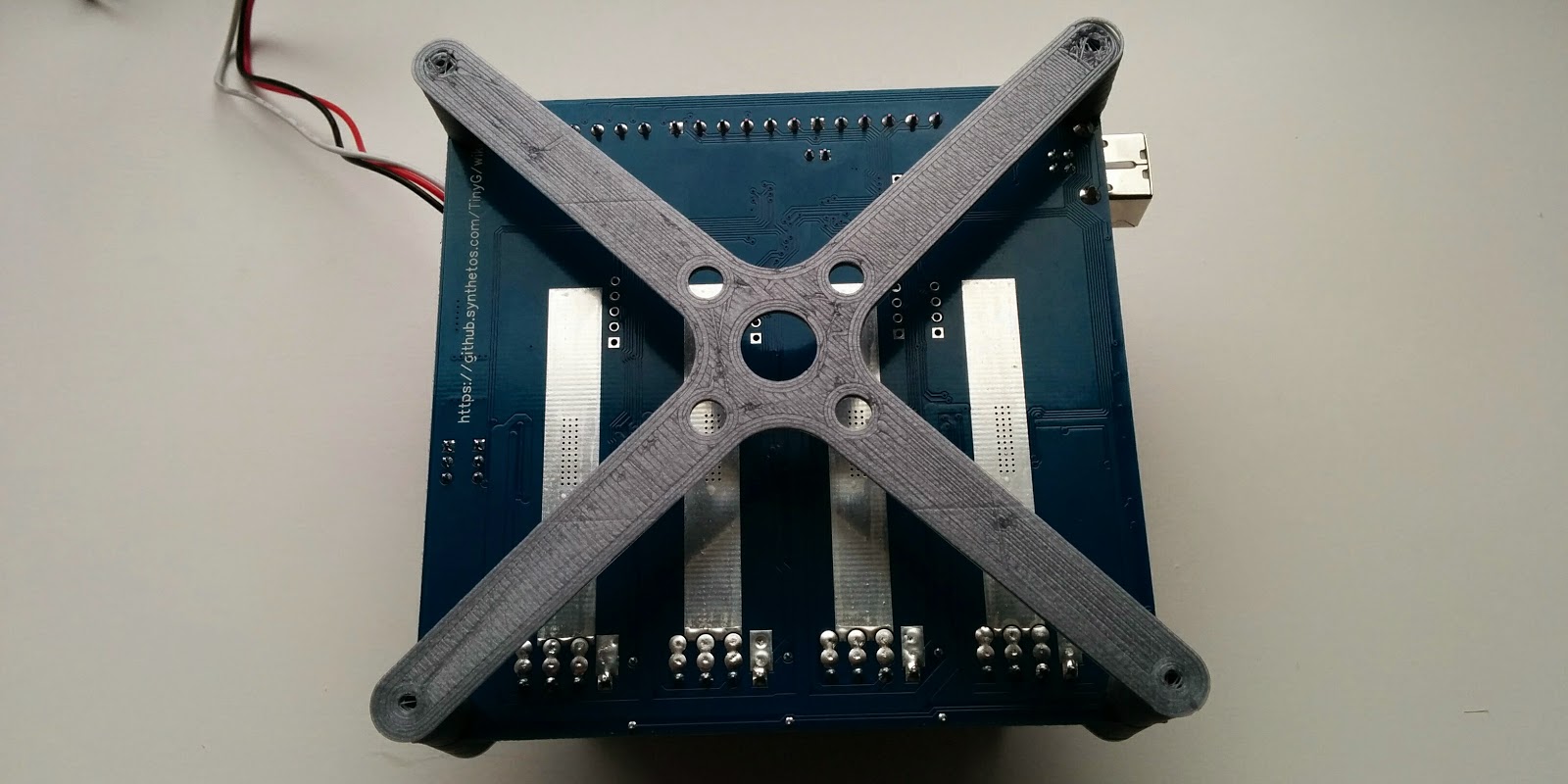
And the upper portion allows for a 12V 80mm cooling fan. The cooling fan should really blow onto the back of the board, and I’ll move things around when I build the metal enclosure.
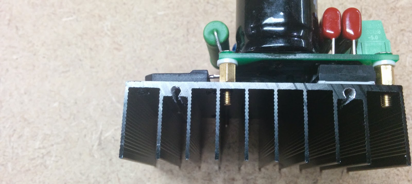
The speed controller had a couple of places that looked like they could be used for mounting holes, so I tapped them for M3:
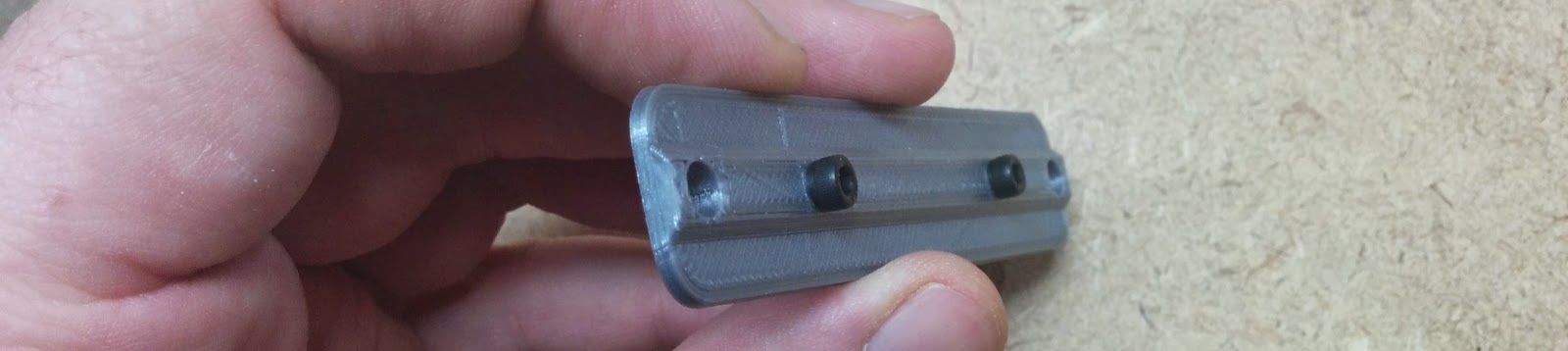
This is the mount for the speed controller:
I also created some T-nut keepers, so I could put some extra T-nuts in the slots nd not have them make vibration noise:
This shows some of the T-nut keepers in use:
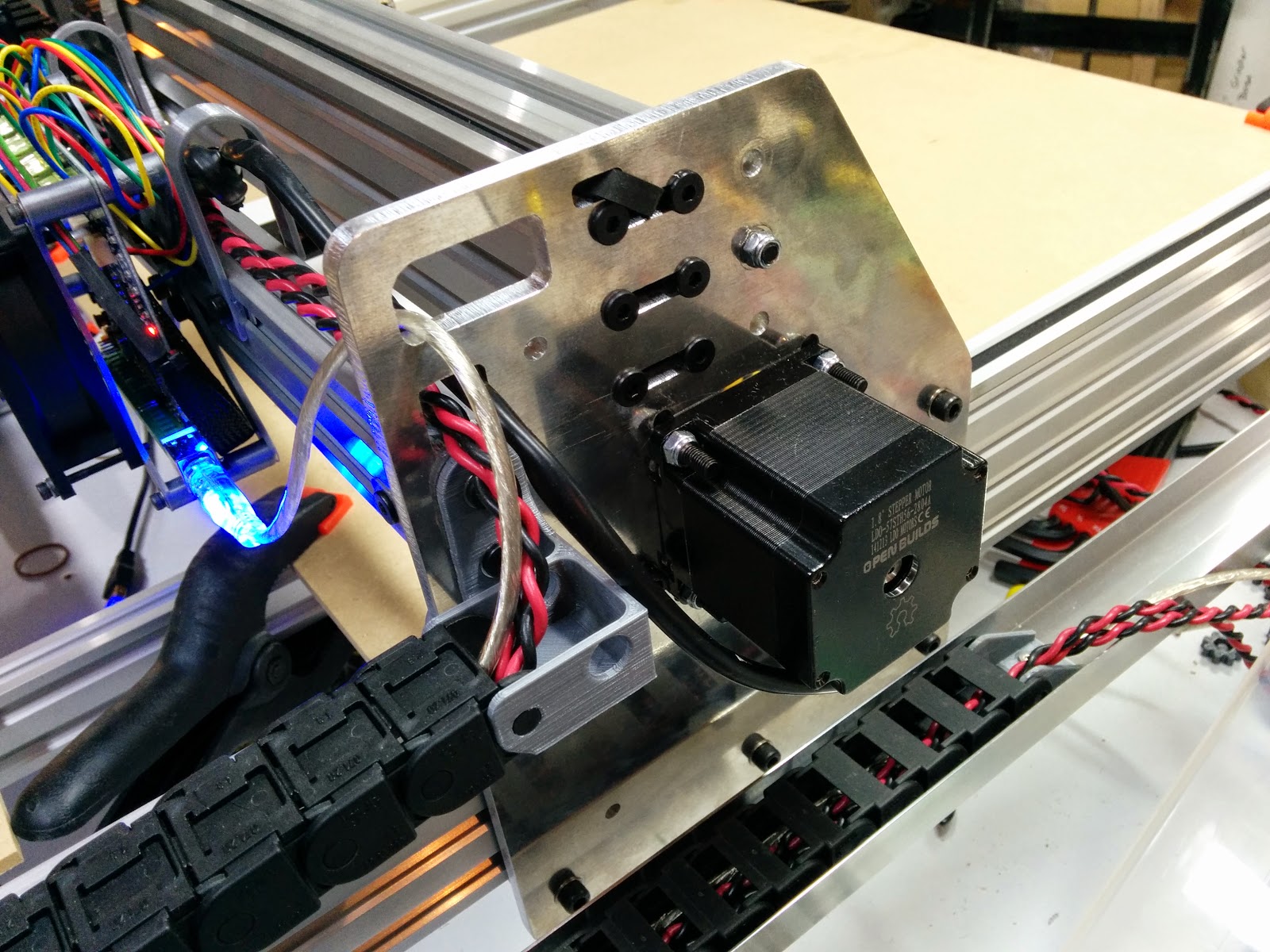
Everything all wired up:

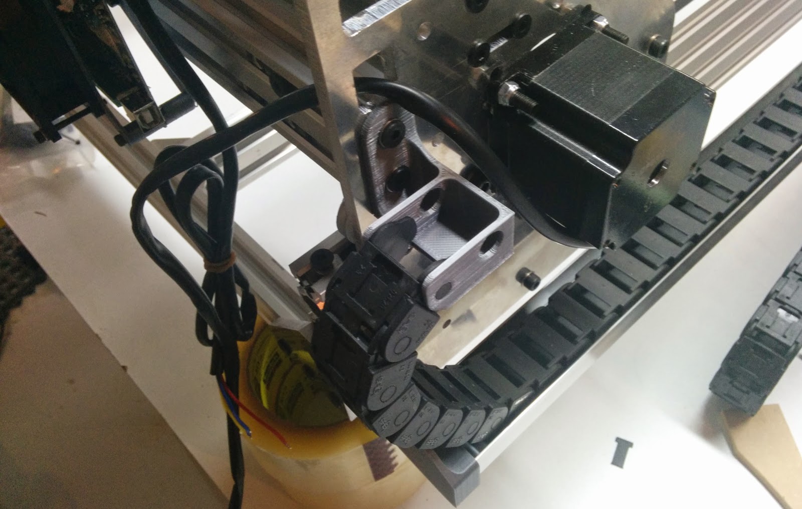
Closeup of the left Y stepper:
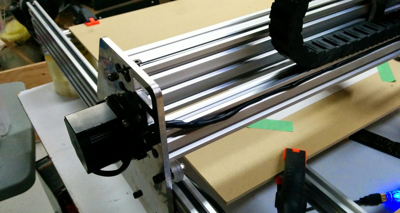
And the right Y stepper:
The top of the X cable chain. I left a piece of string in the cable chain since I still have more wires to pull through (this cable chain didn’t have the “zipper” feature). I used a zap strap to keep the cable loom from fraying and then wrapped it in heat shrink.
Here are some wire clips I designed. The one on the left is secured to the V-Slot using an M5 screw. The one on the right snaps into the V-Slot:
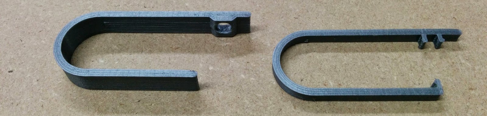
Here’s an example of the screw mounted version:

An the clip on version:
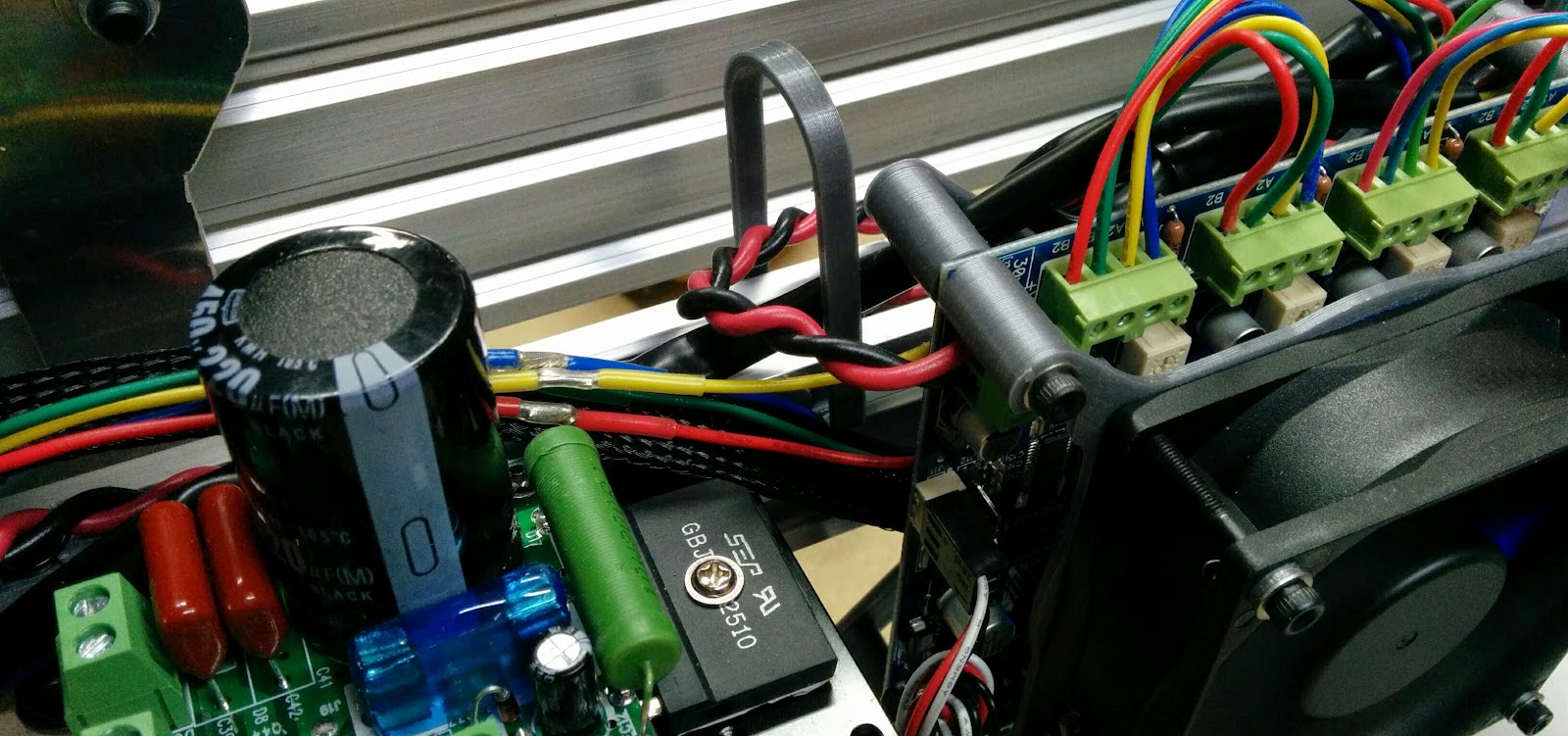
Closeup of the stepper wiring. From left to right is Motor 1 thru 4, X, Y1, Z, and Y2. I wired the NEMA 23 motors (X, Y1, and Y2) all in the same order. For some reason, the NEMA 17 use different colors for the coil pairs, which is why its different.

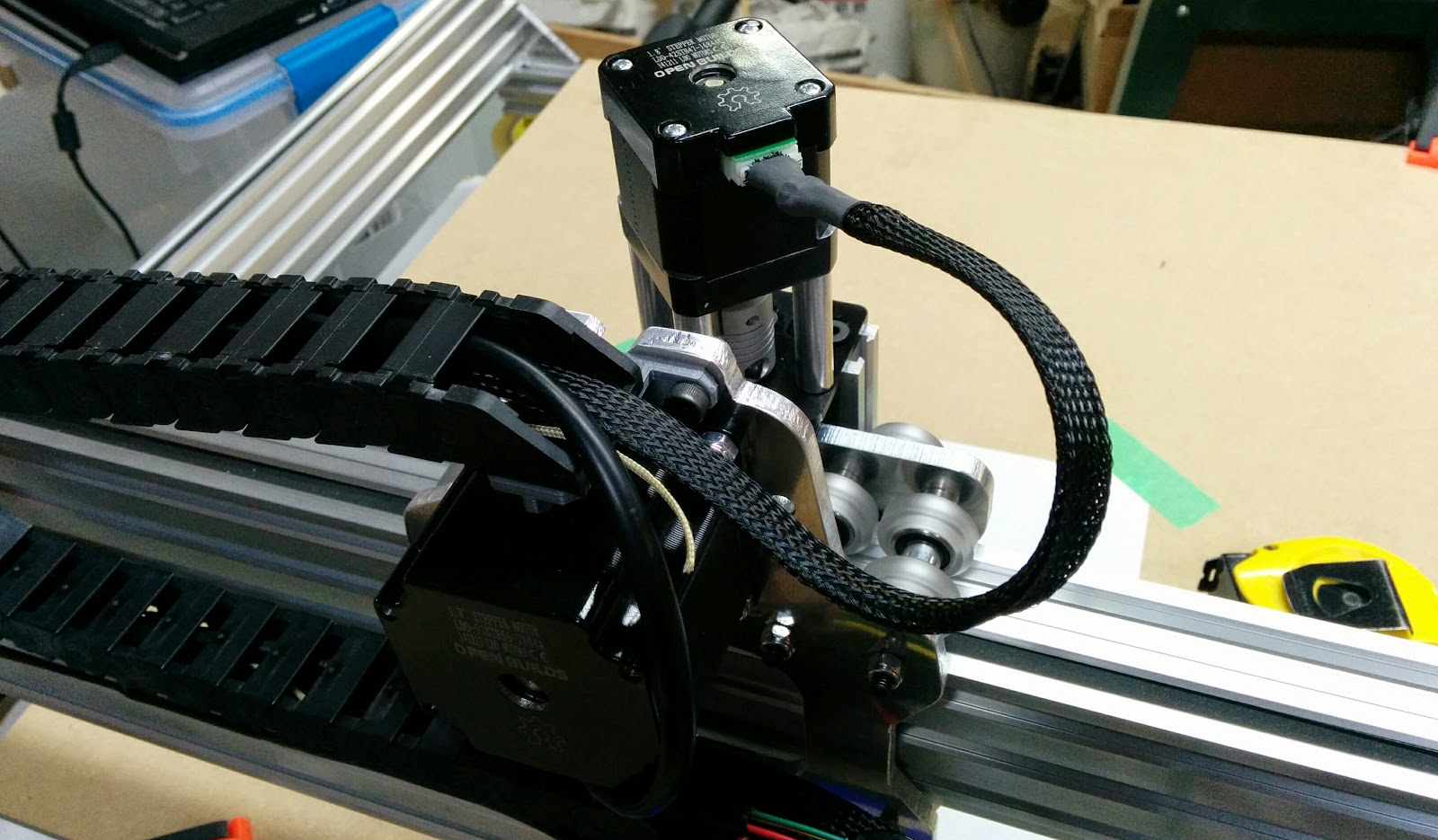
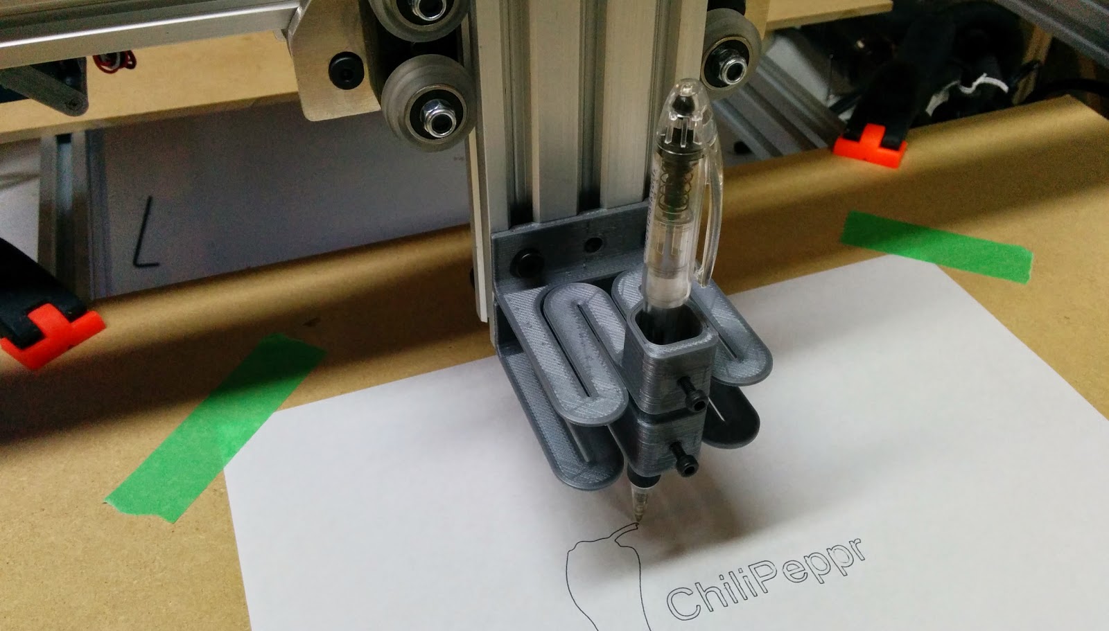
I designed a pen mount, and this is a photo of the pen mount, along with the output of the first gcode file run:
Video clip showing the first gcode run using ChilPeppr:
I set the rapids to 400 mm/sec (24000 mm/min) and here’s a video showing corner to corner moves. That was just my initial guess at a rapid speed, I’ll need to play to find out how fast it can actually go.
3D Printed Parts
| OX-Cable-Chain-Mounts | OnShape | github (STEP & STL) |
| Spindle-Driver-Mount | OnShape | github (STEP & STL) |
| TinyG-Mount | OnShape | github (STEP & STL) |
| Wire-Clips | OnShape | github (STEP & STL) |
| T-Nut-Keeper | OnShape | github (STEP & STL) |
| Pen-Holder | OnShape | github (STEP & STL) |
Related: Unboxing, Part 1, Part 2, Part 3, Part 4, Part 5, Part 6, Clamps