OX Build - Part 2
NOTE: I recommend changing the order of things a bit. I mentioned this in part 3 but I thought I would edit my Part 2 post to mention that. Basically, I think that its easier to assemble the entire Z-assembly, put the X-axis extrusions through it and then mount that whole thing on the side plates.
Anways, on with the original post…
Related: Unboxing, Part 1, Part 2, Part 3, Part 4, Part 5, Part 6, Clamps
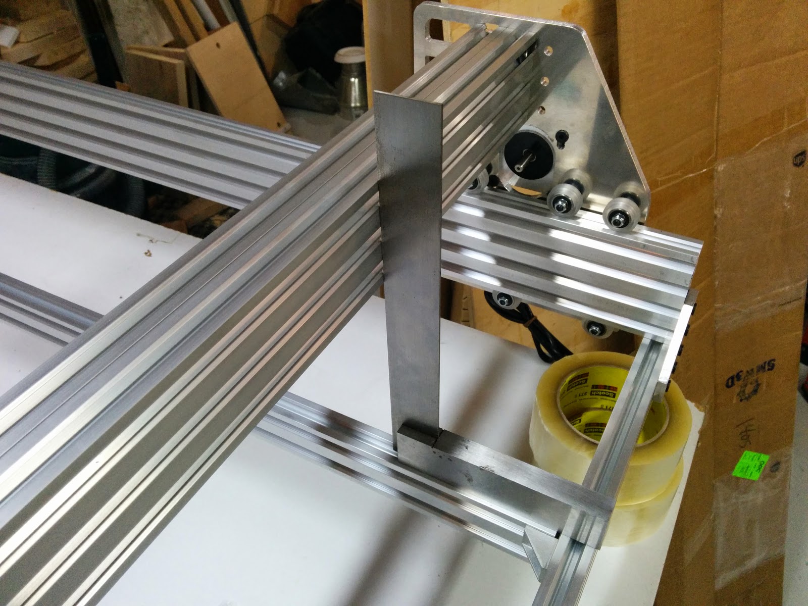
When squaring up the gantry, you want the front face of the gantry to be perpendicular to the bed:
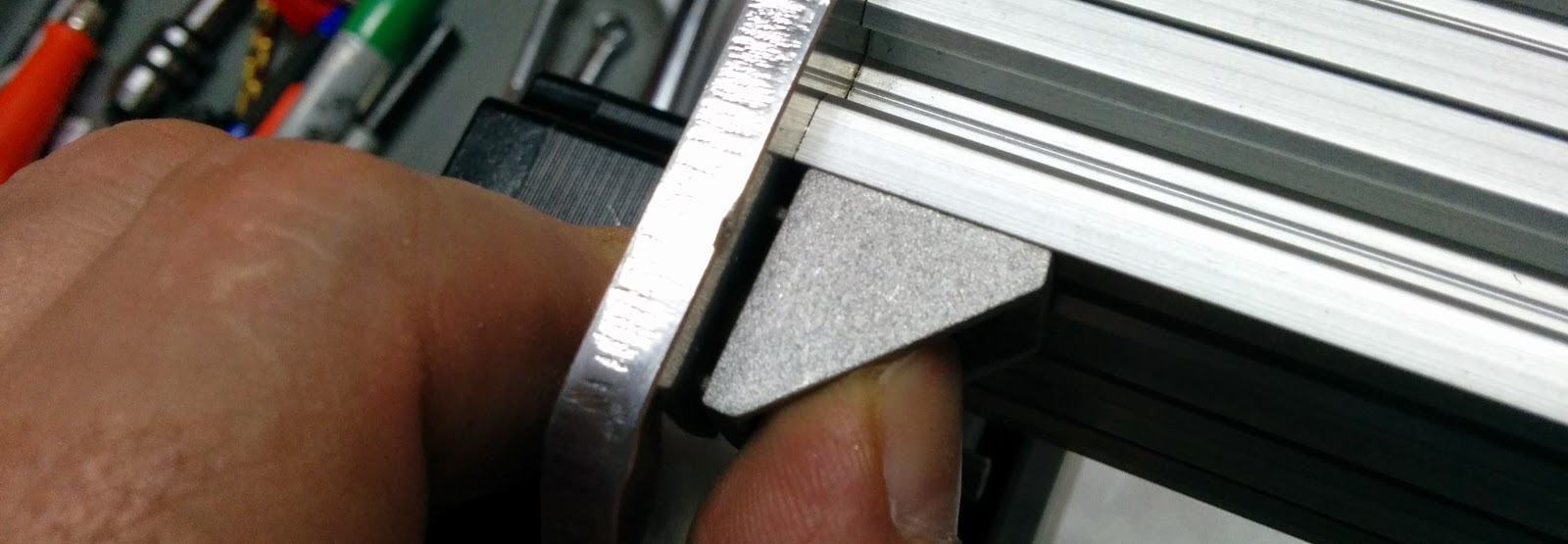
The corner brackets have nubs on both faces, and one set of nubs needs to be filed off.
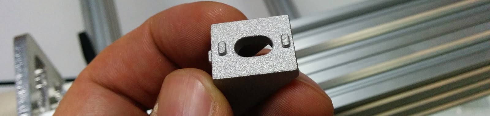
Otherwise it doesn’t mate with the plate:
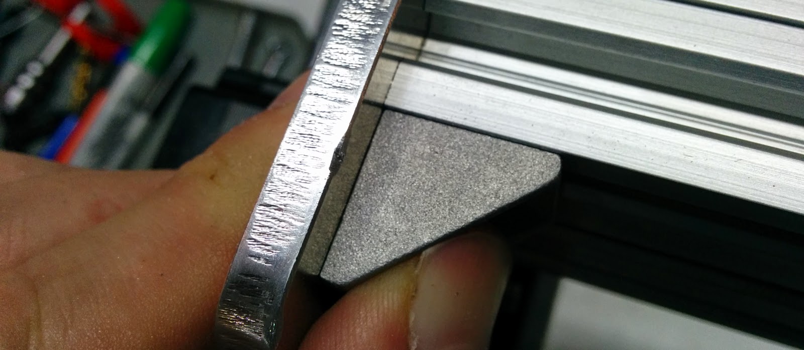
This is the bracket with the nubs filed off:

Which fits much better.
Here’s the left side of the Z axis (with the eccentrics):
And the right side with the regular spacers.
Once again, even ith the eccentrics at the loosest, I had difficulty getting the extrusion on, and when I did get it on, it was very stiff. Fortunately, there was enough slop in the screw holes, that if I loosened everything off and then retightened, the axis finally moved without much effort.

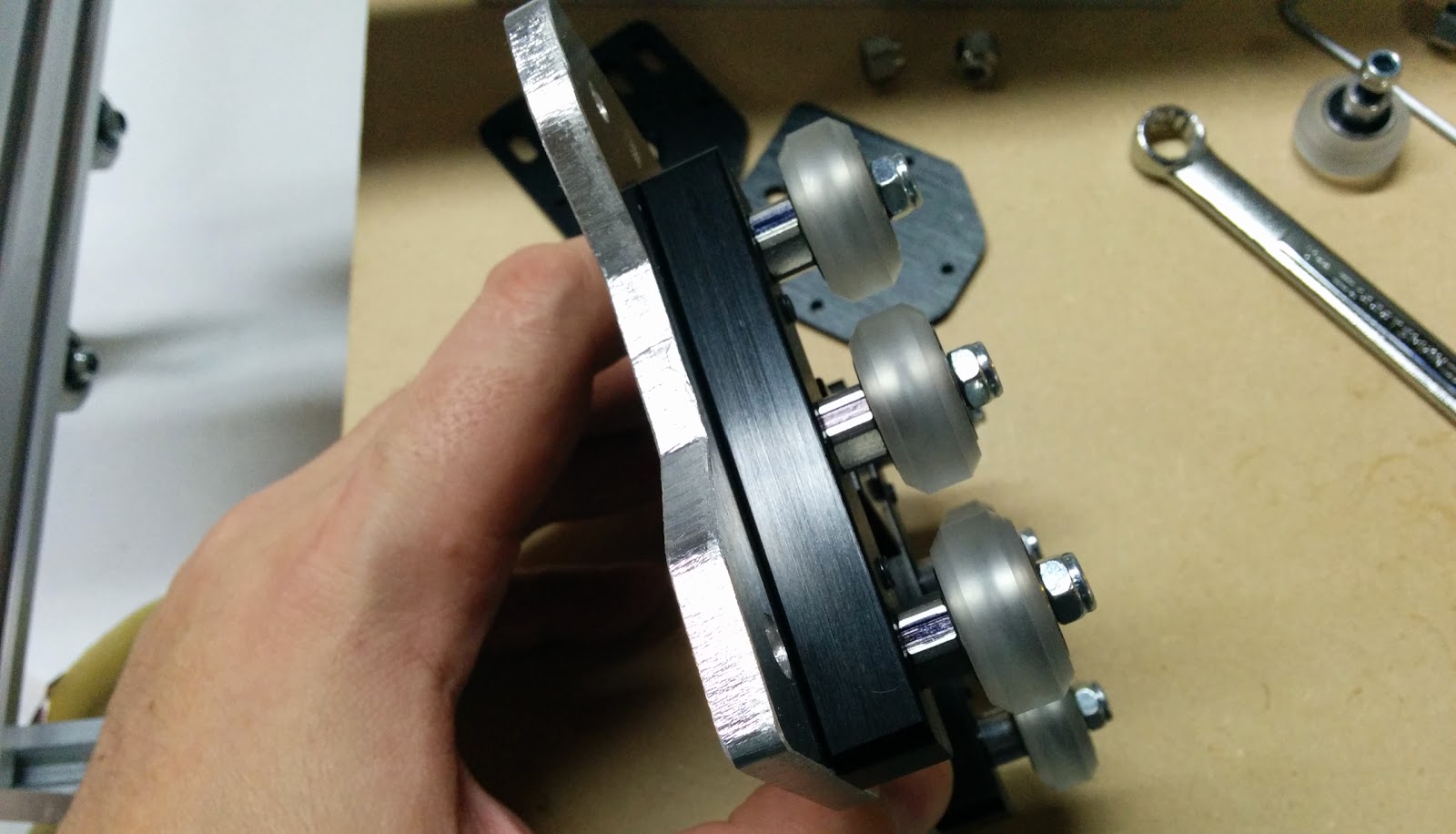
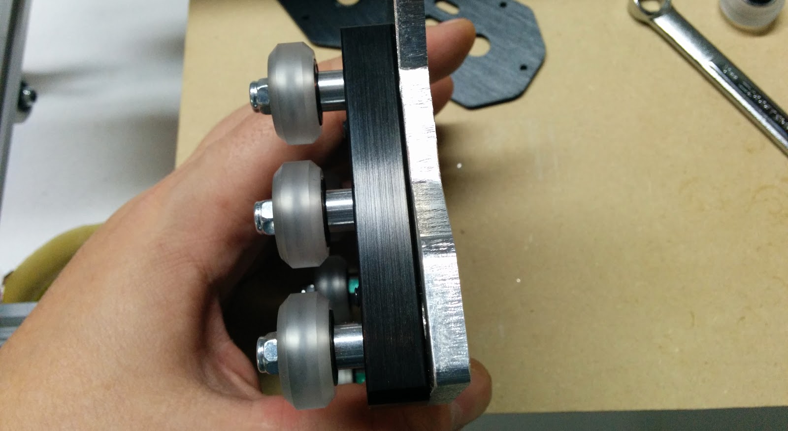
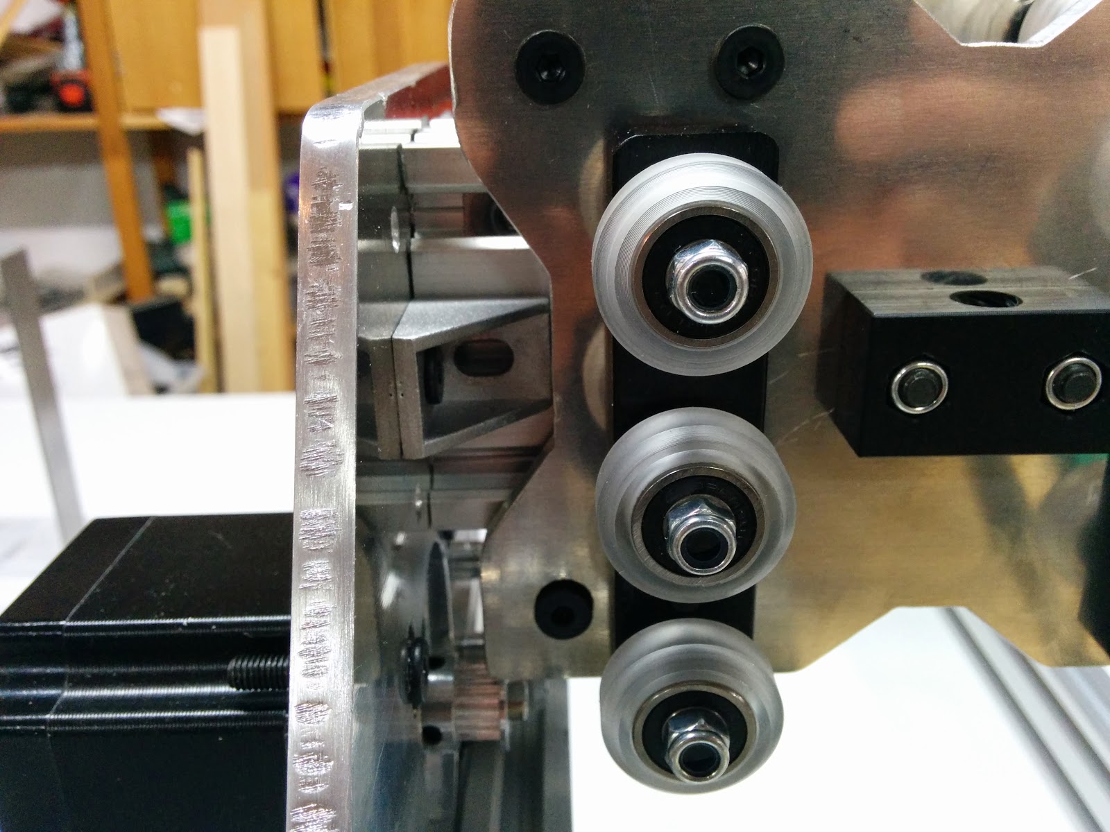
For assembling the remaining wheels, I found it easier to do all 4 at the same time (note that there is a full spacer and a 3mm spacer between the wheels):
Keep the back nuts loose and then you can hang this on the gantry.
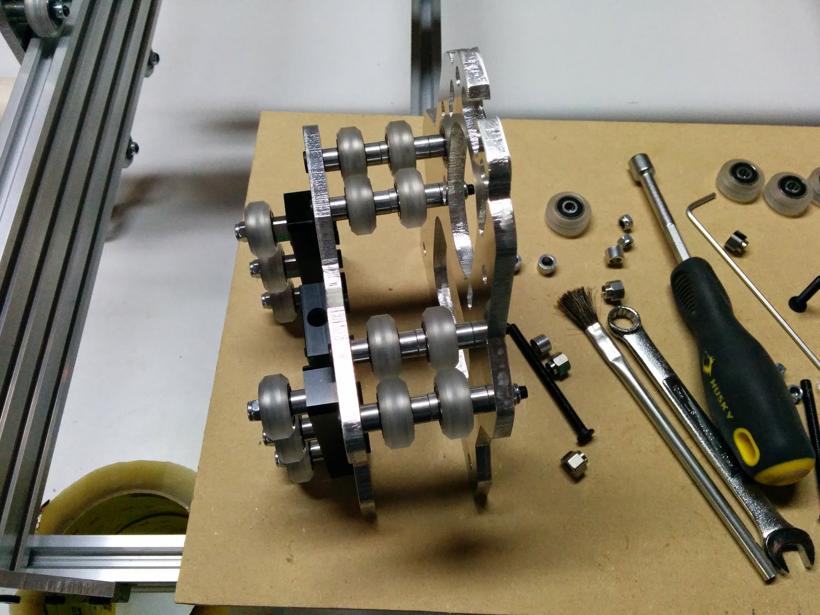
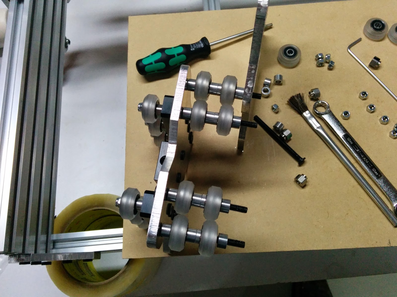
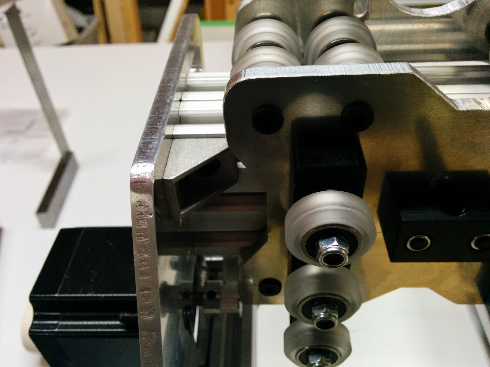
There was no way I could get the bottom bolts in with the 2 bottom wheels. This picture showss the problem using the 20x60 for the axis. It just doesn’t fit. I downloaded the DXF for the plates, and the holes in the plates I got were bang on with the measurements from the DXF, so I have to conclude that the poly wheels are just a wee bit bigger or wider than the delrin wheels.
I wound up drilling the 4 eccentric holes out with an 8.5mm drill before I could get everything to fit (the holes in the DXF or 0.281” or 7.14mm). I decided to drill the holes out rather than filing since the holes were already in a consistent position an I felt drilling would more consistently enlarge the holes versus filing.
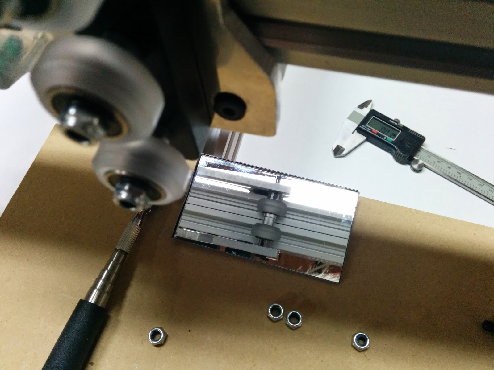
Using a mirror helps to get everything in place. Having the upper 4 nuts extremely loose also helps (there is an eccentric on each side, so you want the plates loose enough that you move the plate over the eccentric.
The manual that came with my OX suggested putting the 90’s in the top row. I decided to put them in the middle row instead.
I lowered the stepper to the lowest position that I could with the allen wrench on top of the extrusion:
With the bracket in the middle and the stepper lowered, I got a little more movement in X-axis. If I ever remake my x plates, I’ll take a bit more off near the middle so that the X plate can come all of the way over to the side.
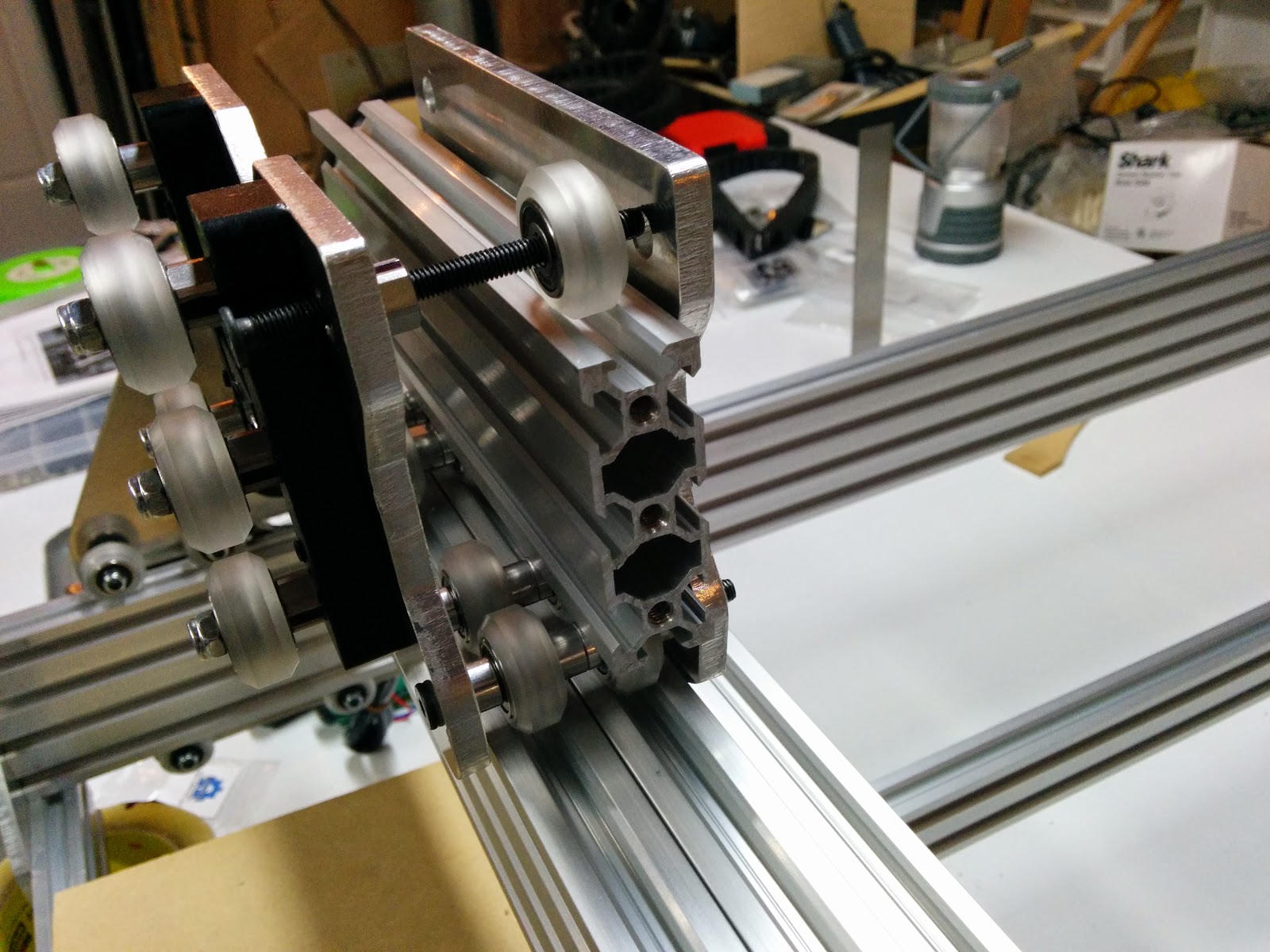
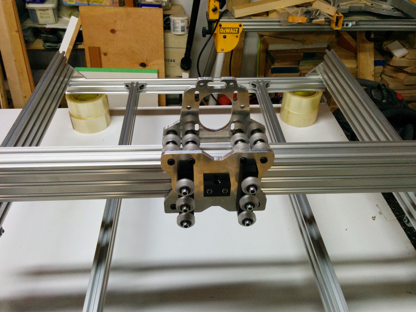
Here’s the X gantry in place:
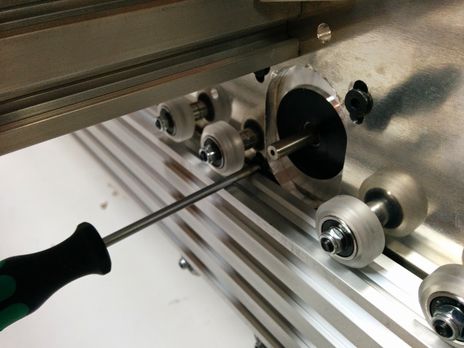
When I opened up my bags with the bearings in it, I discovered that they had literally fallen apart. I machined up some Delrin replacements on my lathe, figuring that they would work until I got replacements, and then I remembered that I had some thrust bearings. The thrust bearings are the right size and more appropriate for this application than radial bearings anyways.

Footnote: I heard from Brandon at SMW3D that they switched bearing suppliers after seeing this post, and he sent me replacement bearings from the new supplier. The new bearings look good, so I thought that deserved a special mention.
Trying to get the poly wheels to fit wound up taking a while, so that’s as far as I got today.
Related: Unboxing, Part 1, Part 2, Part 3, Part 4, Part 5, Part 6, Clamps